Installation
FLOWSIC100 Flare · Addendum to Operating Instructions · 8025365/V1-0/2020-05 · © SICK Engineering GmbH 57
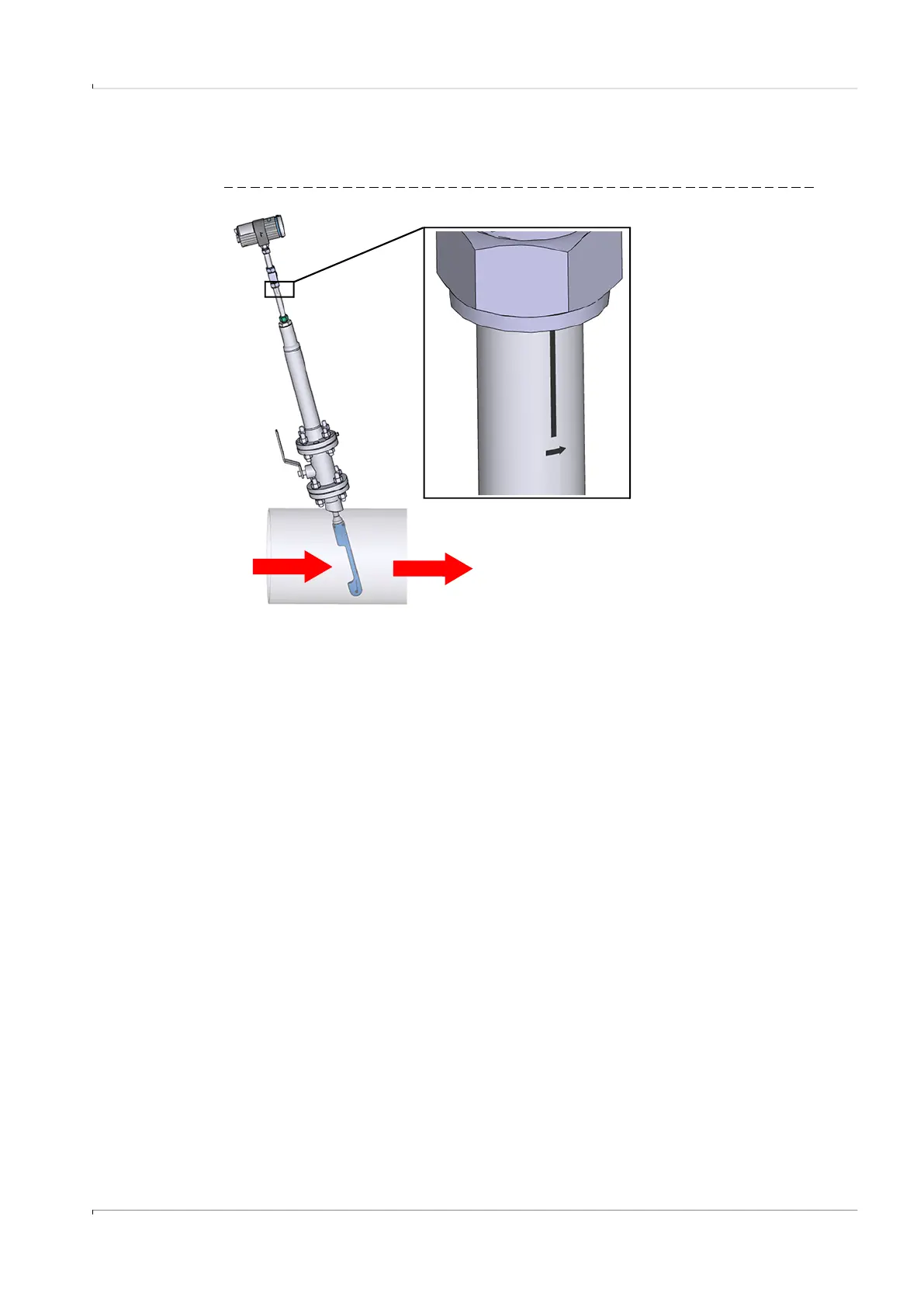
The measuring path must be aligned in flow direction, i.e. the arrow shown must point in
flow direction.
Fig. 34 Marking on probe version F1F-P
▸
Align the measuring path of probe version F1F-P as shown, see → Fig. 35. The maxi-
mum deviation of the angle of rotation of the probe to the flow direction may be +/- 3°.
▸
The electronic housing is aligned horizontally to the path length. If the probe is installed
vertically in the pipeline, a spirit level can be placed laterally on the housing for align-
ment. For horizontal installation, the spirit level can be placed on the housing.
▸
Tighten the self-cutting ring fitting 1.25 turns after alignment.
Make sure the markings for the self-cutting ring fitting are next to each other again,
→ Fig. 32.
Flow direction

 Loading...


