For your safety
FLOWSIC100 Flare · Addendum to Operating Instructions · 8025365/V1-0/2020-05 · © SICK Engineering GmbH 15
2.5.3
Permissible gas temperature, depending on the temperature code of the sender/
receiver units
Case 1 (see → Table 2):
Under normal atmospheric conditions, an explosive atmosphere categorized as Zone 1 or
Zone 2 exists outside the pipeline. Process conditions in the pipeline can differ from the
atmospheric conditions. Process conditions can be in the range specified on the type plate
of the sender/receiver units. In this case the gas or gas mixture can be combustible but
must not be explosive.
Case 2 and 3 (see → Table 2):
On both sides of the pipeline an explosive atmosphere exists under normal atmospheric
conditions. The pipe wall separates different zones, i.e. Zone 1 exists inside the pipe and
Zone 2 outside. This means gas temperature and line pressure may not exceed the
specified ambient values.
NOTICE:
The pipe wall can separate different hazardous areas (zones).
Table 2 Permitted gas temperature for temperature code
Classified
tempera-
ture code in
the hazard-
ous area
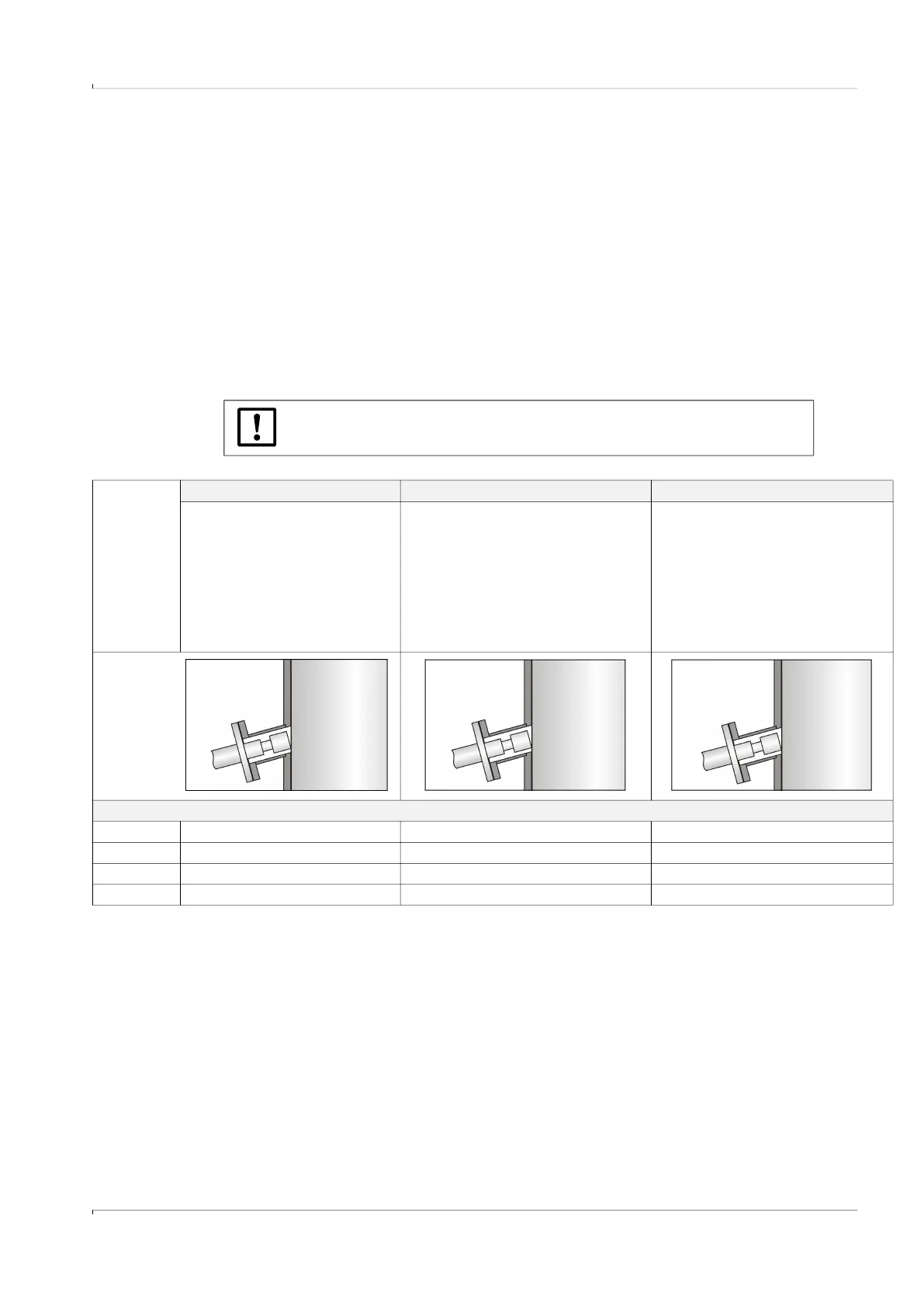
Case 1 Case 2 Case 3
● Ultrasonic sensor outside
explosive atmosphere Zone
1 or 2
● Electronics in explosive
atmosphere Zone 1 or 2
● Gas pressure and gas
temperature according to
specification on device label
● Ultrasonic sensor in explosive
atmosphere Zone 1 or 2
● Electronics in explosive
atmosphere Zone 1 or 2
● Gas pressure and gas tempera-
ture according to ambient specifi-
cation of device
● Ultrasonic sensor in explosive
atmosphere Zone 0
● Electronics in explosive
atmosphere Zone 1 or 2
● Gas pressure atmospheric, gas
temperature max +60 °C
● Not for F1F-H
The sender/receiver units can be used with the following gas temperatures:
T6 -196
1)
… +80 °C -196
1)
… +55 °C -50 … +55 °C
T4 -196
1)
… +130 °C -196
1)
… +70 °C -50 … +70 °C
T3 -196
1)
… +195 °C -196
1)
… +70 °C -50 … +70 °C
T2 -196
1)
… +280 °C -196
1)
… +70 °C -50 … +70 °C
1)
For F1F-H: -70 °C
Non-Ex
atmosphere
Zone 1 or 2
Zone 1 or 2
Zone 1 or 2
Zone 0
Zone 1 or 2

 Loading...


