42 FLOWSIC100 Flare · Addendum to Operating Instructions · 8025365/V1-0/2020-05 · © SICK Engineering GmbH
Installation
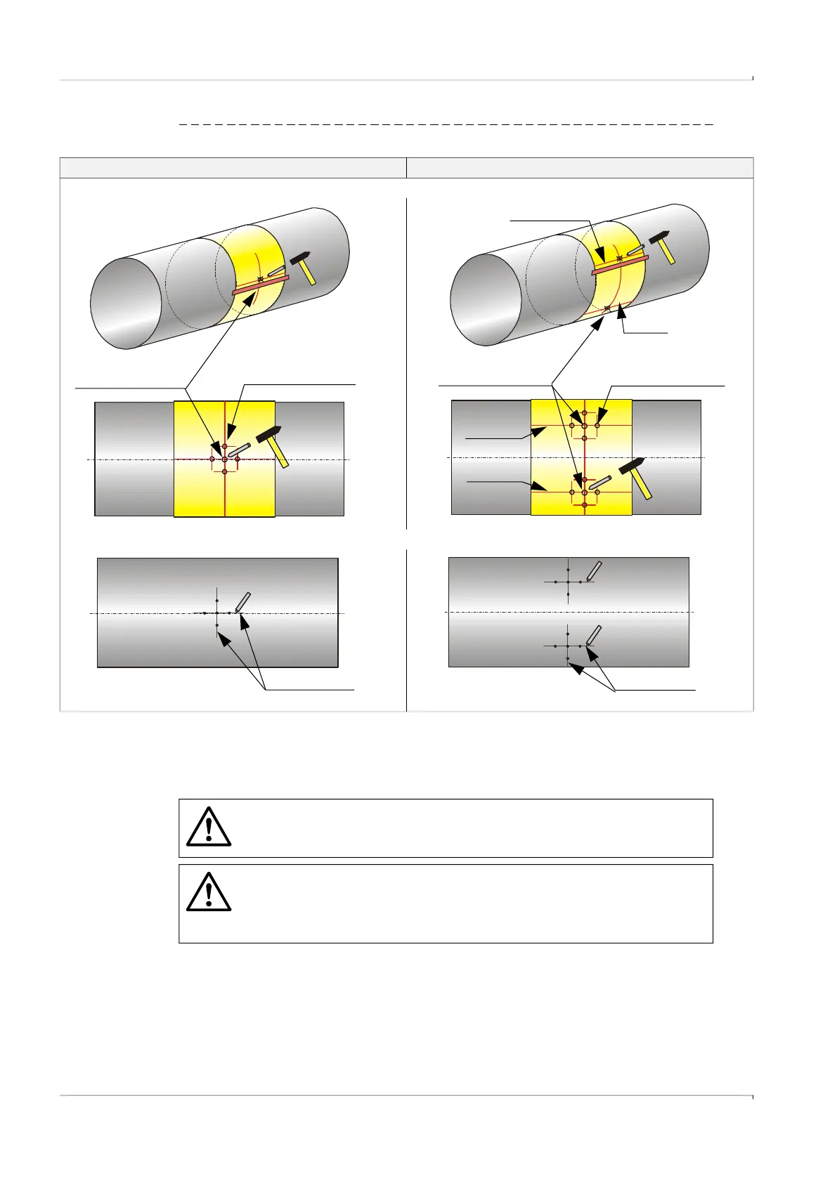
Fig. 22 Marking the nozzle position(s) on the pipeline for the probe version
4.7.4
Welding the nozzle on
Use the installation tool that corresponds to the nozzle to be welded on the pipeline to carry
out the following work.
1-path measurement 2-path measurement
6) Roll the strip back around the pipeline and mark the nozzle positions with crossing and marking points by using a metal center punch.
7) Take the strip off again and join the additional markings with a line.
Crossing point (marking for
the center of the nozzle)
Marking point (aid for
aligning the nozzle)
Path 1
Path 2
Path 1
Path 2
Marking point (aid for
aligning the nozzle)
Crossing point (marking for
the center of the nozzle)
Marking lines
Marking lines
WARNING: Hazards through combustible gases or high pressure
If “hot tapping” is not used, depressurize the pipeline and flush free of
flammable gases before starting the work.
WARNING: Risk of explosion/health hazard
A faulty welding seam can allow gas to escape from the pipeline. This can
▸
Ensure welding seams are gas-tight.
▸
Check strength and durable tightness of the welding seams.
 Loading...


