Installation
FLOWSIC100 Flare · Addendum to Operating Instructions · 8025365/V1-0/2020-05 · © SICK Engineering GmbH 43
▸
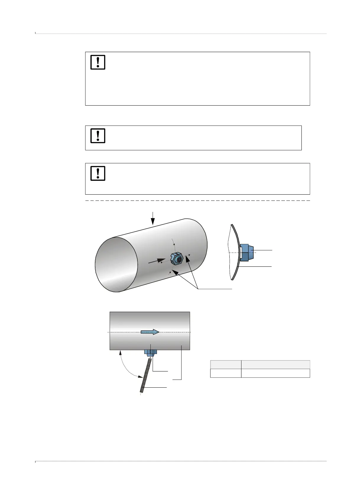
Position the welding aid (1) on the pipeline (2) as shown in → Fig. 23.
▸
Screw in threaded rod (3) with the sharp tip in the welding aid.
Fig. 23 Positioning of the welding aid
▸
Slide centering plate (4) on the cone of the welding aid (1) and fasten with the nut (5).
▸
Slide nozzle (6) over threaded rod and centering plate.
▸
Place the centering (7) into the nozzle opening so that the marking on the centering
corresponds to the nozzle type (ANSI or DIN, size).
NOTICE:
● Any welding and installation work on pipelines may only be carried out by
authorized personnel with a specific qualification.
● Special qualified and approved procedures have to be followed. This proce-
dure requires the written agreement by the plant operator.
● The general safety requirements and all other plant operator instructions
have to be followed.
NOTICE:
Check the welding aid position after welding. The deviation from the drawn
lines must not be more than 0.5 mm. Otherwise reposition the welding aid.
NOTICE:
The threaded rod is fitted by the manufacturer with a clamp ring. This is to aid
removal of the centering plate following installation of the nozzles. The clamp
ring should therefore not be removed.
1
2
View A
A
Marking lines
View B
Angle Type FLSE100-XT
75 ° F1F-S, F1F-M, F1F-H, F1F-P
1
3
Flow direction
1 Welding aid
2 Pipeline
3 Threaded rod
2
View B

 Loading...


