13
8027872/1JTM/0-8/2023-05| SICK O P E R A T I N G I N S T R U C TI O N S | FLOWSIC550
Subject to change without notice
PRODUCT DESCRIPTION 3
3.3 System components
The FLOWSIC550 measuring system comprises:
● the meter body with a straight pipe section with ultrasonic measuring paths and an inte-
grated flow conditioner,
● the signal processing unit (SPU) measurement and interface electronic,
● optional pressure and temperature sensors for the volume conversion device option.
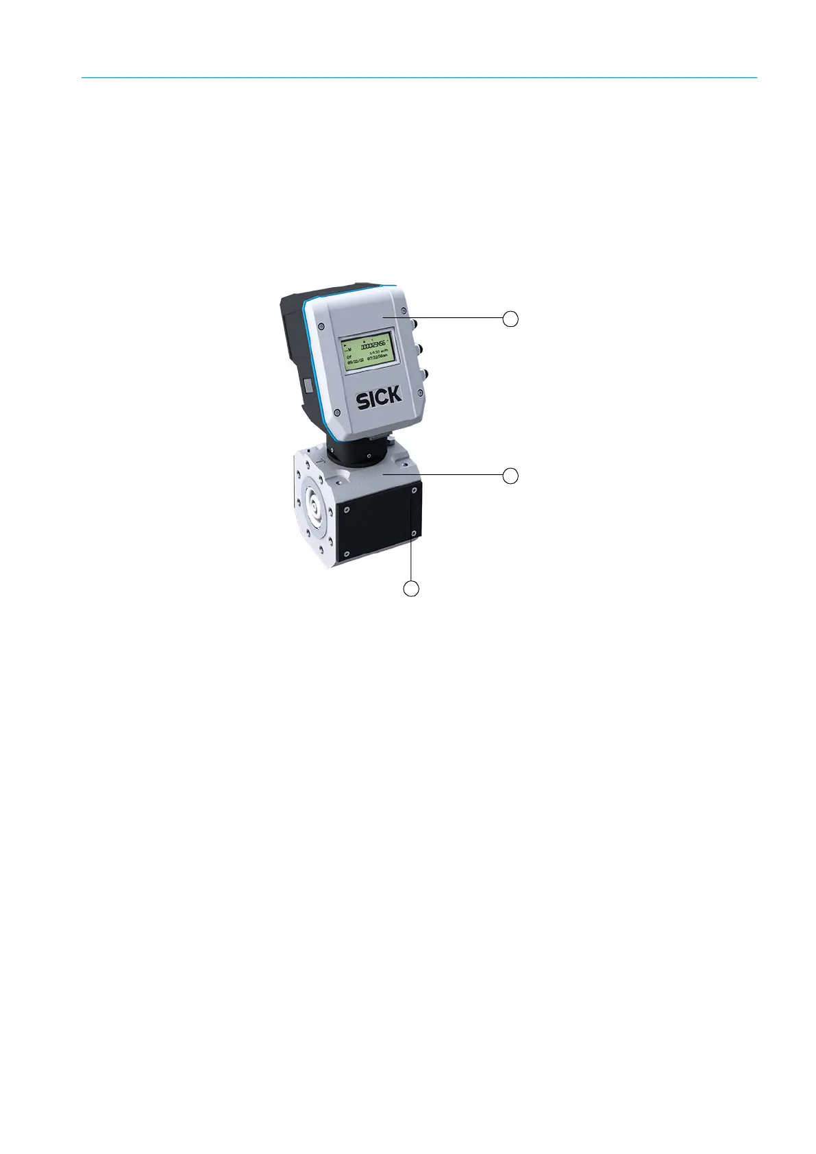
Fig. 1: FLOWSIC550 components
3.3.1 Meter body
The meter body is available in various flange standards and fitting lengths to connect the
gas flow meter to the system pipeline. Depending on the version, the adapter is designed
for assembly on line flanges CL300 or CL600 in accordance with ASME B16.5.
An internal flow conditioner rectifies the gas flow in the gas flow meter so that flow profile
disturbances caused by pipe bends in the inlet or outlet sections or components projecting
into the pipe (e.g. a thermowell) are negligible on measuring results.
3.3.2 Ultrasonic transducers
Ultrasonic transducers optimally tuned to system requirements are fitted on the measuring
device. The high quality of the transducer design provides the basis for accurate and highly
stable transit time measurement of the ultrasonic signals.
1
1 Signal processing unit (SPU)
2 Meter body
3 Cover for ultrasonic transducers
2
3