30
8027872/1JTM/0-8/2023-05| SICKO P E R A T I N G I N S T R U C T I O N S | FLOWSIC550
Subject to change without notice
7 ELECTRICAL INSTALLATION
7.5 Installing the pressure and temperature sensor
Pressure sensor
Temperature sensor
The temperature sensor must be installed in the customer's pipeline downstream of the
measuring point.
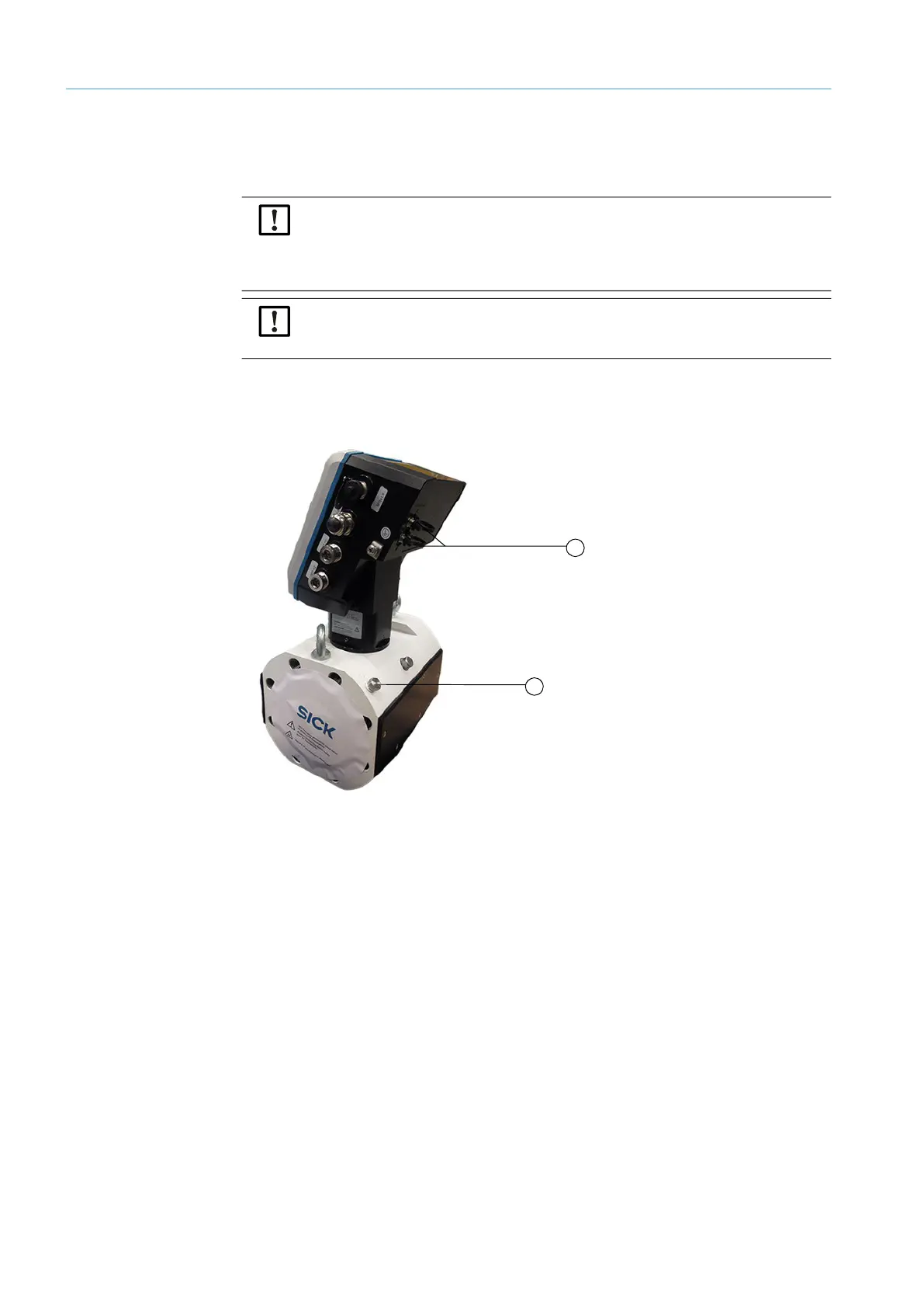
Fig. 6: Connecting the pressure and the temperature sensor
NOTICE:
● The pressure measuring port to be used for measurement is marked “P
M
”.
● The thread on the meter body is damaged when a wrong thread type is screwed in.
When the meter body has an NPT 1/4“ thread, screw in the adapter from NPT 1/4“
to G1/4“ (Part No. 2075562) before using the accessory parts available from SICK.
NOTICE:
Ensure sufficient clearance to the wall or other components at the rear measuring port
when installing the sensor.
1 M8 connectors for connection of pressure and tempera-
ture sensor
2 Pressure measuring port “P
M
”
1
2