•
The device can be aligned in the X- and Y-axes.
•
The mounting system must be able to bear the weight of the device and connect‐
ing cables without shock.
•
Mounting options for the device using the threaded mounting holes must be
available.
5.3 Mounting location
5.3.1 Determining alignment
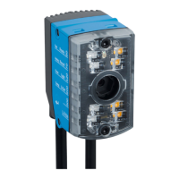
Alignment at maximum reading field width:
Figure 5: Mounting opposite to the direction on motion of the AGV
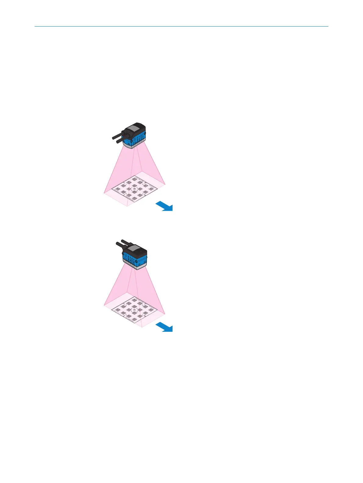
Alignment at maximum transport speed of the AGV:
Figure 6: Mounting in direction of motion of the AGV
The selected alignment effects the speed of the AGV and the size of the field of view
depending on the set working distance and the 2D codes used, see "Typical reference
values during operation", page 55.
5.3.2 Working range
The possible working range for reading is 50 mm to 300 mm.
5 MOUNTING
22
O P E R A T I N G I N S T R U C T I O N S | GLS611 8026021//2020-12-18 | SICK
Subject to change without notice