Table 10: Data transmission rates and recommended max. cable lengths
Interface Data transmission rate Distance to the target computer
(host)
RS-232 Up to 19.2 kBd Max. 15 m
38.4 kBd ... 57.6 kBd Max. 5 m
115.2 kBd … 500 kBd < 2 m
NOTICE
Risk of damage to the internal interface modules!
If the serial data interfaces are wired incorrectly, then electronic components in the
device could get damaged.
■
Observe the information on wiring.
■
Carefully check the wiring prior to switching on the device.
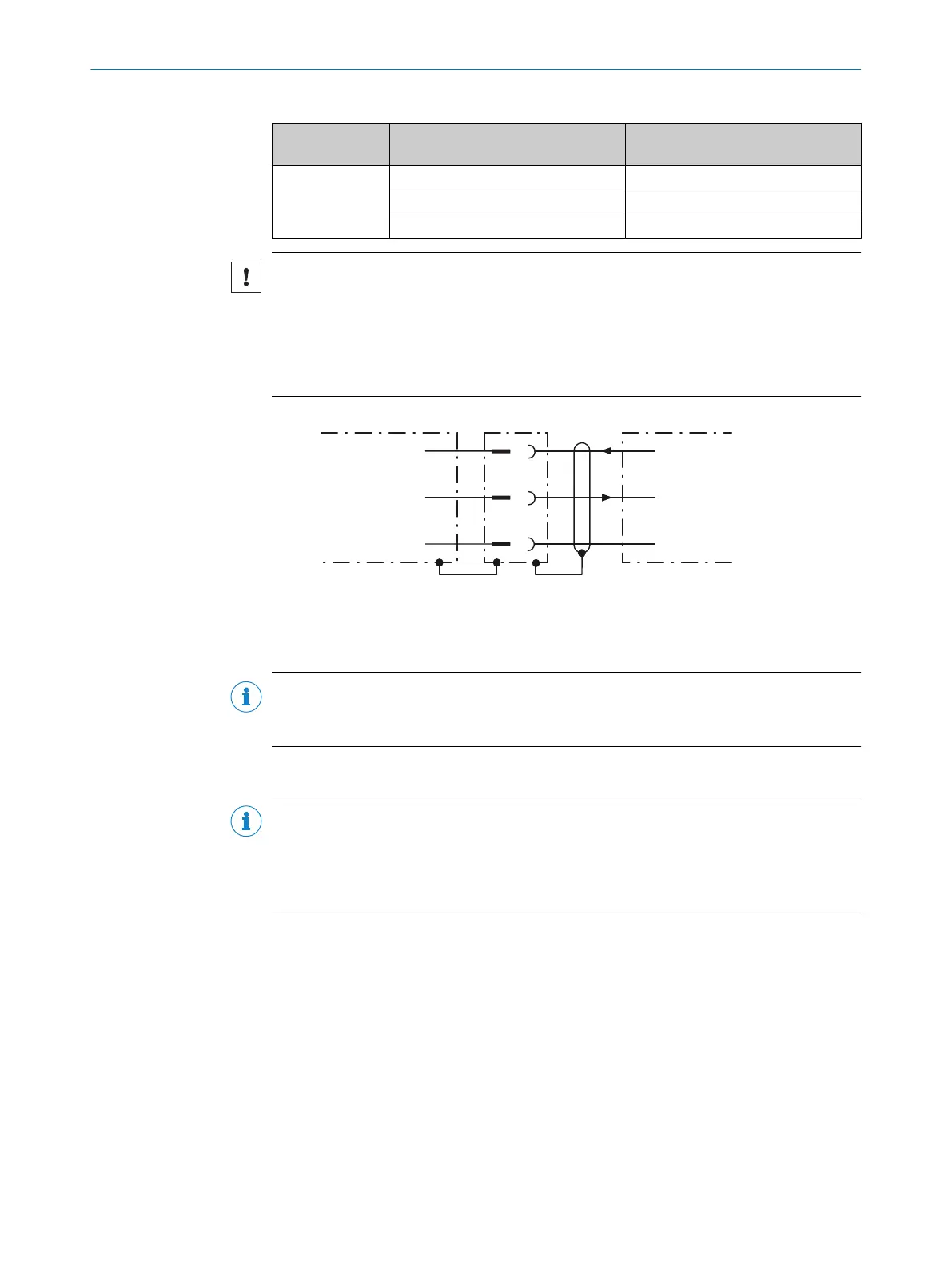
RS-232
!
"
§
Device 1 Host
TxD
RxD
GND
RxD
TxD
GND
Figure 19: Wiring of the serial data interface RS-232 (host)
1
Device
!...§
Pin assignment: see RS-232 pin assignment for the respective device
NOTE
Activate the serial data interface type in the device using a configuration tool, e.g. the
SOPAS ET configuration software.
6.5.3 Wiring the CAN interface
NOTE
Activate the CAN data interface in the device with a configuration tool, e.g. the configu‐
ration software SOPAS ET.
Make further settings in the device corresponding to the function of the device in the
system configuration.
6.5.4 Wiring the digital inputs
The two digital inputs “Sensor 1” and “Sensor 2” can be used, for example, for starting
and/or ending the external read cycle or for feeding an incremental signal.
The full complement of digital inputs is available at each of the following locations:
•
Male connector of the device cable (M12, 17-pin, A-coded)
•
Adapter cable (female connector, M12, 17-pin, A-coded/male connector, D-Sub-
HD, 15-pin)
•
Open end of the adapter cable (female connector, M12, 17-pin, A-coded/open
end)
6 ELECTRICAL INSTALLATION
36
O P E R A T I N G I N S T R U C T I O N S | GLS611 8026021//2020-12-18 | SICK
Subject to change without notice