6.3.2 Connection principle for read mode
"Ethernet"
(Host)
GLS611
Image display
SOPASSOPAS
"Power/Serial Data/
CAN/I/O"
(Host)
HOST
PC
Further data
processing
"Ethernet" (AUX
image transfer) 3
EthernetEthernet
Cable 2
4
6
Reading result 5
V
S
1
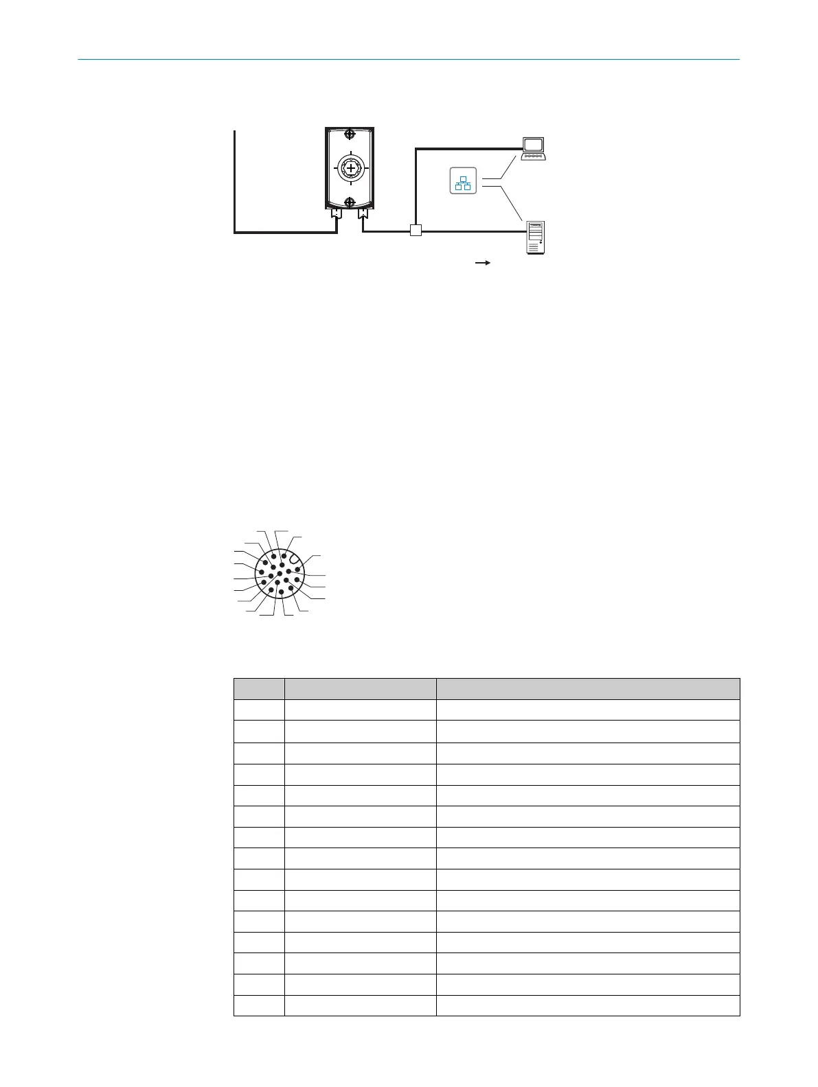
Figure 16: Connection block diagram for read mode
1
Supply voltage V
S
2
Cable with open end
3
Ethernet, Aux interface (image transmission)
4
Image display
5
Read result
6
Data further processing
6.4 Connection diagrams
6.4.1 Power/Serial data/CAN/I/O connection example
3
1
7
2
6
5
4
8
13
14
17
15
9
10
12
16
11
Figure 17: Male connector, M12, 17-pin, A-coded
Table 6: Pin assignment of the “Power/Serial data/CAN/I/O” connection
Pin Signal Function
1 GND Ground
2 V
S
Supply voltage
3 CAN L CAN bus (IN/OUT)
4 CAN H CAN bus (IN/OUT)
5 – –
6 TxD (RS-232), host Host interface (sender)
7 – –
8 – –
9 SensGND Digital input ground
10 Sensor 1 Digital input 1
11 – –
12 RxD (RS-232), host Host interface (receiver)
13 Result 1 Digital output 1
14 Result 2 Digital output 2
15 Sensor 2 Digital input 2
ELECTRICAL INSTALLATION 6
8026021//2020-12-18 | SICK O P E R A T I N G I N S T R U C T I O N S | GLS611
33
Subject to change without notice