Pin Signal Function
16 Result 3 Digital output 3
17 – –
– – Screen
NOTE
Limitations in the options for backing up the parameter set
The device does not come with an AUX serial interface.
A current and application-specific parameter set created in SOPAS ET can therefore only
be manually saved and archived as a project file on the computer.
NOTE
Using an additional extension cable
•
If the serial interface (RS-232) is not being used, the maximum total length of
cable is 30 m.
•
If the serial interface (RS-232) is being used, the maximum total length of cable is
15 m.
•
Wire diameter: at least AWG26 (0.14 mm
2
).
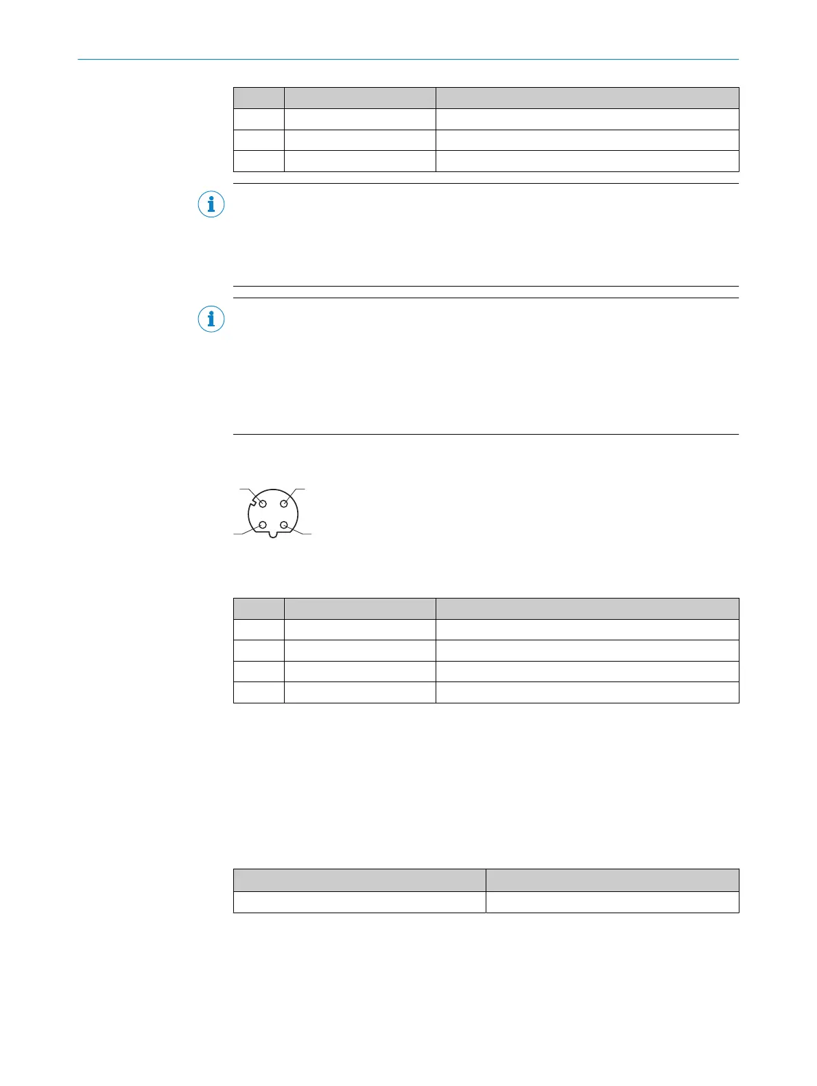
6.4.2 Ethernet connection
Figure 18: M12 female connector, 4-pin, D-coded
Table 7: Pin assignment of the “Ethernet” connection
Pin Signal Function
1 TD+ Sender+
2 RD+ Receiver+
3 TD– Sender–
4 RD– Receiver–
6.5 Connecting the device
6.5.1 Connecting the supply voltage
Voltage source in accordance with ES1 and PS2 (EN 62368-1) or SELV and LPS
(EN 60950-1).
The power source for the device must be able to provide the following power outputs:
Table 8: Required supply voltage V
S
Supply voltage V
S
Power source: required power output
1)
DC 12 V ... 24 V ± 15% Maximum 16 W
1)
For device with 3 loaded digital outputs (each 50 mA).
6 ELECTRICAL INSTALLATION
34
O P E R A T I N G I N S T R U C T I O N S | GLS611 8026021//2020-12-18 | SICK
Subject to change without notice