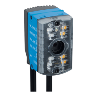
5
Target focus position setting
6
Actual focus position setting
7
Green LED = focus position has been adjusted to suit the working distance (actual status
= target status)
8
Focus position coincides with the working distance (actual status = target status)
1. Mount and align the device at the required working distance.
✓
The LED that lights up red indicates the currently set focus position on the device.
✓
The LED that lights up blue indicates the working distance at which the device is
mounted.
2. Attach the focus adjustment tool to the optics.
3. Rotate the focus adjustment tool to align the focus position with the working
distance that has been set:
°
To align the focus position with a larger working distance, rotate the focus
adjustment tool in the clockwise direction.
°
To align the focus position with a smaller working distance, rotate the focus
adjustment tool in the counterclockwise direction.
NOTICE
Risk of damaging the product!
If too much force is applied when rotating the focus adjustment tool, the product
can be damaged.
■
Use a maximum torque of 60 Ncm when rotating the focus adjustment tool.
✓
As the tool is rotated, the red LED continuously indicates the current focus posi‐
tion.
✓
When the LED of the set working distance lights up green, the focus position is
aligned with the working distance.
4. Check the focus position again when commissioning the device using the
SOPAS ET configuration software and, if necessary manually align the focus set‐
ting with the help of the focus adjustment tool.
NOTE
The working distance that the device measures using the time-of-flight sensor is
displayed in SOPAS ET in the ToF distance (mm) parameter. The currently set focus
position is displayed in SOPAS ET in the Focus position (mm) parameter.
5.4 Mounting the device
1. Using the threaded mounting holes provided (see "Setup and dimensions",
page 14) mount the device on a prepared mounting system using at least two
M4 screws. Screw the screws no more than 5 mm into the threaded mounting
holes. Use the threaded mounting holes pairwise on the left and right side of the
device. For alternative mounting, carefully screw the two M3 screws (length: at
least 35 mm) into the through holes on opposite sides of the device. Optional:
Attach the separately ordered SICK mounting system to the device. Mounting
systems are available as accessories, see "Accessories", page 54.
NOTICE
Damage to device through improper mounting.
•
Do not screw the M4 screws right through to the other side of the device!
•
To fasten the device, carefully screw only M3 screws (length: min 35 mm) into
the through holes on opposite sides of the device.
5 MOUNTING
26
O P E R A T I N G I N S T R U C T I O N S | GLS611 8026021//2020-12-18 | SICK
Subject to change without notice