–y
+y
–x +x
1
2
4
5
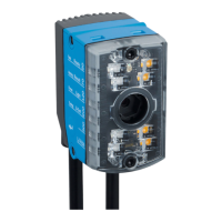
α = 270°
α = 180°
α = 0°
3
α = 90°
Figure 10: Mounting bracket α
1
Coordinate system of the field of view
2
Angle α = 0° (default value), direction of motion according to + x
3
Angle α = 90°, direction of motion according to + y
4
Angle α = 180°, direction of motion according to - x
5
Angle α = 270°, direction of motion according to - y
NOTE
If problems with reflections occur, use a polarizing filter (part number: 2088228), see
"Accessories", page 54.
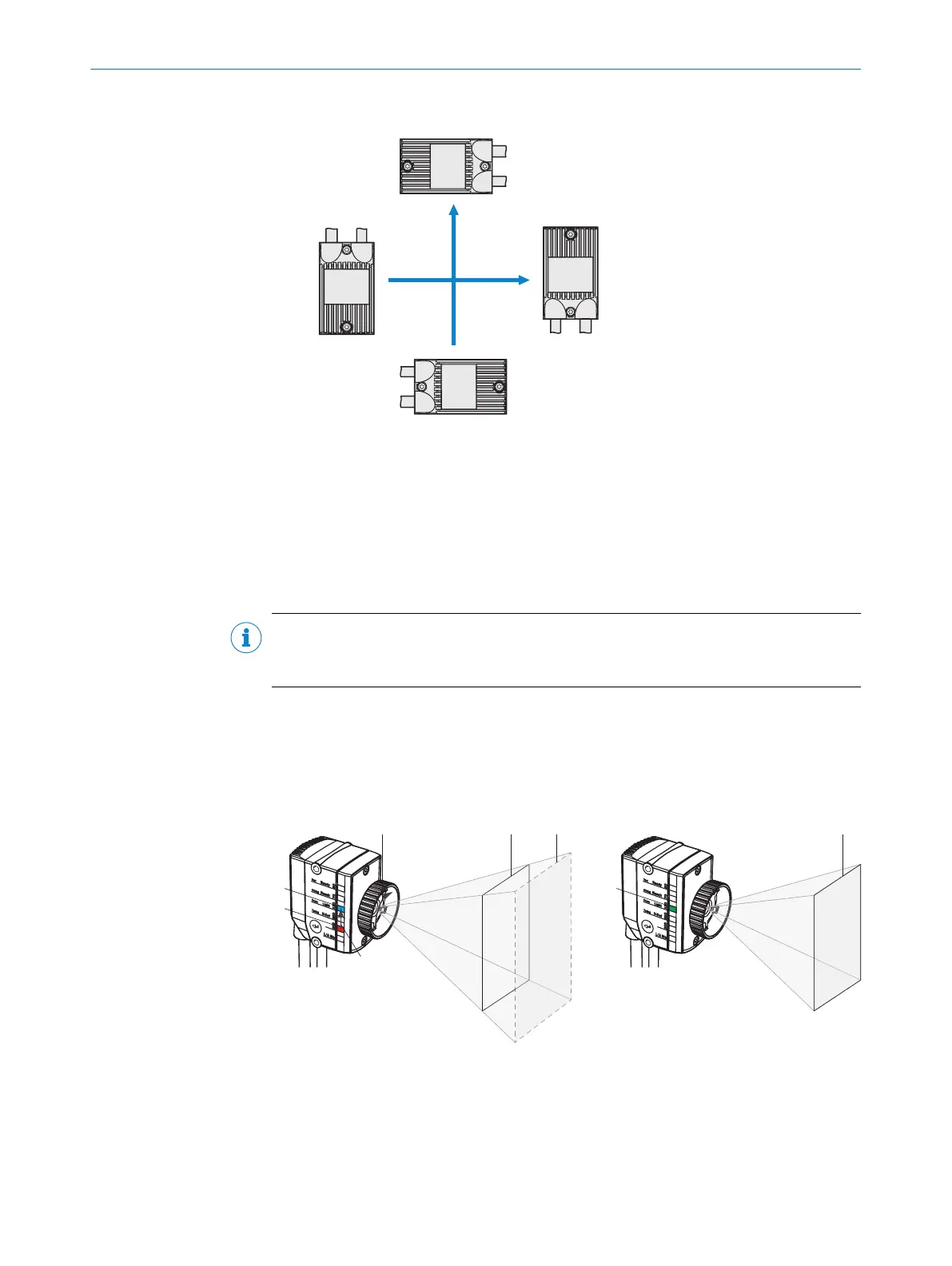
5.3.4 Adjusting the focus position
The user adjusts the focus position to suit the required working distance with the help
of the focus adjustment tool. The focus position is valid for one working distance. The
device does not perform automated tracking (auto focus) if, for example, the working
distance changes significantly. The focus adjustment tool is included with delivery.
Figure 11: Manually adjusting the focus position with the help of the focus adjustment tool
1
Red LED = the focus position set
2
Blue LED = current working distance
3
Rotate the focus adjustment tool
4
The red LED (current focus position) is made to approach the blue LED (current working
distance) by turning the focus adjustment tool.
MOUNTING 5
8026021//2020-12-18 | SICK O P E R A T I N G I N S T R U C T I O N S | GLS611
25
Subject to change without notice