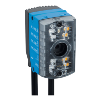
Table 9: Typical current consumption depending on supply voltage
Designation Supply voltage (V
S
) in [DC V]
10.2
(12 V -15%)
12 24 27.6
(24 V +15%)
Current consumption, digi‐
tal outputs unloaded
I
B RMS
[A] 0.290 0.244 0.128 0.110
Power loss, digital outputs
unloaded
P
RMS
[W] 2.96 2.93 3.07 3.04
Maximum current con‐
sumption, digital outputs
unloaded
I
B Peak
1)
[A] 1.06 0.848 0.387 0.331
Typical, all 3 digital outputs
loaded (0.05 A per output)
I
B RMS 3Out
[A]
0.44 0.394 0.278 0.26
Power loss, all 3 digital out‐
puts loaded (0.05 A per
output)
P
Peak 3Out
[W]
14.6 15.09 15.61 15.831
1)
For design of the power supply unit, supply cable and fuse protection at the start of the line.
Protecting the supply cables
To ensure protection against short-circuits/overload in the customer’s supply cables,
the wire cross-sections used must be appropriately selected and protected.
The following standards must be observed in Germany:
•
DIN VDE 0100 (part 430)
•
DIN VDE 0298 (part 4) and/or DIN VDE 0891 (part 1)
Connection without connection module
With a supply voltage of DC 12 V to 24 V ± 15%, protect the device with a separate fuse
with value 2 A.
b
Install the fuse in the supply circuit at the start of the supply cable.
6.5.2 Wiring data interfaces
Wiring Ethernet interface
1. Connect the device to the Ethernet connection of the computer via the adapter
cable.
2. Set up communication via the SOPAS ET configuration software.
NOTE
The Ethernet interface of the device has an Auto-MDIX function. This automatically
adjusts the transmission speed as well as any necessary crossover connections.
Wiring the serial data interface (host)
NOTE
The serial data interface is available only as a host interface for this device.
The maximum data transmission rate for the serial interface depends on the length of
cable and on the type of interface. Observe the following recommendations:
ELECTRICAL INSTALLATION 6
8026021//2020-12-18 | SICK O P E R A T I N G I N S T R U C T I O N S | GLS611
35
Subject to change without notice