Operating Instructions
LMS5xx
Electrical installation
8013796/ZM63/2017-05-09 © SICK AG · Germany · All rights reserved · Subject to change without notice 65
Chapter 6
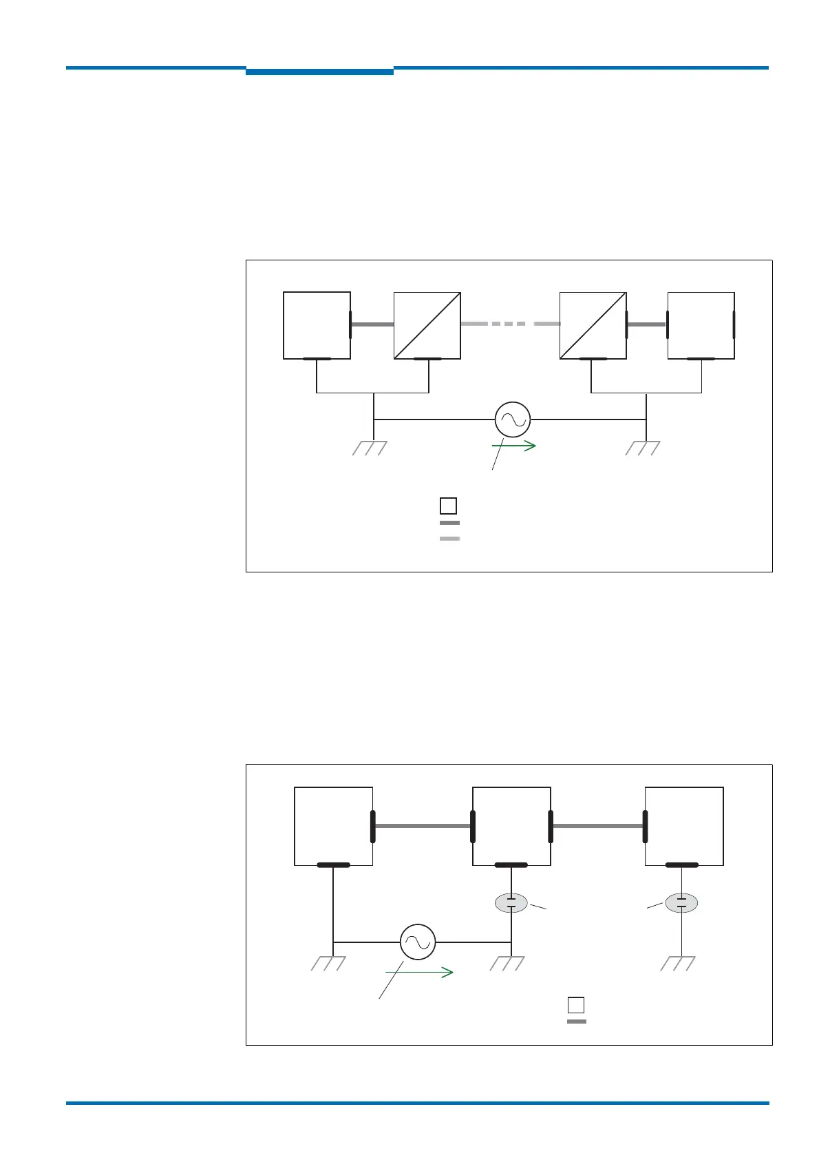
a) Measures for widely distributed system installations
On widely distributed system installations with correspondingly large potential differences,
we recommend setting up local islands and connecting them using commercially available
electro-optical signal converters. This measure achieves a high degree of resistance to elec-
tromagnetic interference while at the same time complying with all the requirements of
IEC 61010-1:2010-06.
Fig. 41 shows the function of this measure.
Fig. 41: Use of electro-optical signal converters
The ground loop is opened by using the electro-optical signal converters between the
islands. Within the local islands, a stable equipotential bonding prevents equalizing
currents from occurring at the cable shields.
b) Measures for small system installations
For smaller installations with small potential differences, the insulated installation of the
LMS5xx and the peripheral devices can be a sufficient solution.
Fig. 42 shows the function of this measure.
Fig. 42: Insulated assembly of the LMS5xx and the peripheral devices (sample)
Electro-
optical
converter
PLC LMS5xx
Grounding point 1
Grounding point 2
U
Grounding potential difference
= Shielded electrical cable
= Metal housing
Electro-
optical
converter
= Fiber optic cable
Power
supply
PLC LMS5xx
Grounding point 1 Grounding point 2
U
Grounding potential difference
= Shielded electrical cable
= Metal housing
Electrically insulated
Grounding point 3
 Loading...


