Electrical installation
68 © SICK AG · Germany · All rights reserved · Subject to change without notice 8013796/ZM63/2017-05-09
Operating Instructions
LMS5xx Laser Measurement Sensors
Chapter 6
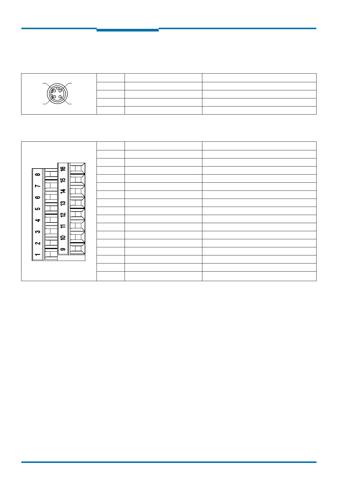
6.3.1 Connections of the LMS500
LMS500 Lite and PRO Indoor: "Ethernet" connection on the system connector
LMS500 Lite Indoor: "Power/Data/I/O" connection in the system connector
Pin Signal Function
1 TX+ Transmitter+
2Rx+ Receiver+
3 TX– Transmitter–
4Rx– Receiver–
Tab. 21: LMS500 Lite and PRO Indoor: Pin assignment of the “Ethernet” connection (4-pin M12 female connector, D-coded)
Terminal Signal Function
1V
S
Power supply sensor
2 GND Ground sensor
3 OUT1 Switching output 1
4 OUT2 Switching output 2
5 OUT3 / OUT Sync Switching output 3 / Output Synchronization
6 IN1 Switching input 1
7 IN Sync Input Synchronization
8 GND IN /IN Sync Ground input 1 / Input Synchronization
9V
S
OUT Power supply switching outputs
10 GND V
S
OUT Ground power supply switching outputs
11 TD+ Transmitter RS-422/RS-232
12 TD–/TxD Transmitter RS-422/RS-232
13 GND RS Ground RS-422/RS-232
14 RD–/RxD Receiver RS-422/RS-232
15 RD+ Receiver RS-422/RS-232
16 Shield RS Shield RS-422/RS-232
Tab. 22: LMS500 Lite Indoor: Terminal assignment of the “Power/Data/I/O” connection (2 x terminal blocks, 8-pole)
 Loading...


