Electrical installation
78 © SICK AG · Germany · All rights reserved · Subject to change without notice 8013796/ZM63/2017-05-09
Operating Instructions
LMS5xx Laser Measurement Sensors
Chapter 6
6.5.4 LMS511/LMS531/LMS581: Connecting the round M12 plug-in connectors
Prerequisites on the device for enclosure rating IP 67
The system connector is plugged on the device, its two screws are tightended.
The device is only connected on the M12 plug-in connectors provided for this purpose.
Only use round plug-in connectors that are compliant with enclosure rating IP 67.
The cables plugged into the M12 round plug-in connections must be screwed tight. Any
electrical connections that are not being used must be fitted with protective caps or
plugs that are screwed tight (as in the delivery condition).
The black, round cover of the USB auxiliary interface ("USB" connection) on the front is
screwed tight.
Pre-assembled cables are available as accessories for the connection to the round M12
plug-in connectors. These comprise the round plug-in connector and 5 m, 10 m or 20 m of
cable with flying leads.
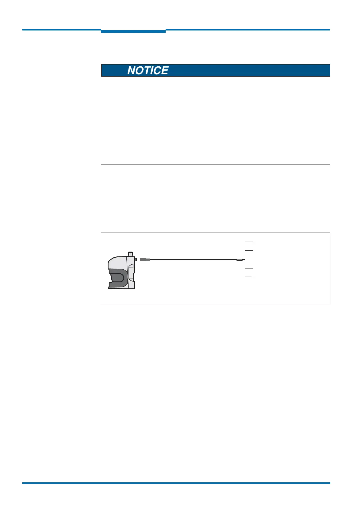
Connection of the voltage supply on the LMS511/LMS531/LMS581
Pre-assembled cables with flying leads are available for the supply to the LMS511/
LMS531/LMS581.
Fig. 45: LMS511/LMS531/LMS581: connection of the voltage supply
On the connection cables part no. 6036159, part no. 6042565 and part no. 6042564 the
wires for GND and GND heating are either blue and black or yellow and green.
The connection cables require the following minimum voltages at the open cable end:
Part no. 6036159, 5 m: 19.2 V
Part no. 6042565, 10 m: 19.7 V
Part no. 6042564, 20 m: 21.4 V
LMS511/LMS531/
LMS581
M12×
5-pin
Blue or yellow = GND
Brown = V
S
Part no. 6036159, 5 m
Part no. 6042565, 10 m
Part no. 6042564, 20 m
Female connector
Black or green = GND heat.
White = V
S
heat.
 Loading...


