Operating Instructions
LMS5xx
Electrical installation
8013796/ZM63/2017-05-09 © SICK AG · Germany · All rights reserved · Subject to change without notice 79
Chapter 6
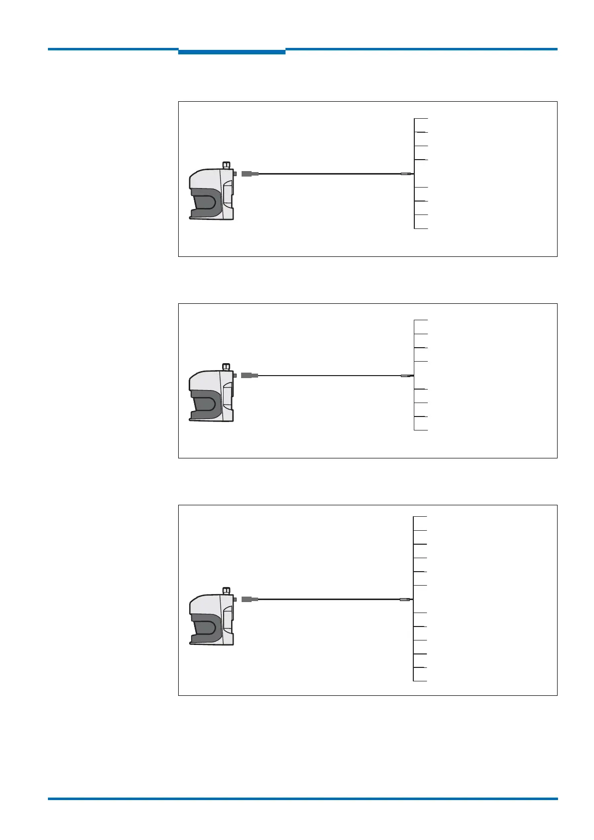
LMS511 Lite: “Data” connection
Fig. 46: LMS511 Lite: “Data” connection
LMS511 Lite: “I/O” connection
Fig. 47: LMS511 Lite: “I/O” connection
LMS511 PRO/LMS581 PRO Security/LMS511 Heavy Duty: “Data” connection
Fig. 48: LMS511 PRO/LMS581 PRO Security/LMS511 Heavy Duty: “Data” connection
LMS511 Lite
Female connector
M12×8-pin
Part no. 6036153, 5 m
Part no. 6028420, 10 m
Part no. 6036154, 20 m
Yellow = TD+ (RS-422)
Green = RD+ (RS-422)
White = RD–/RxD (RS-422/
RS-232)
Pink = NC (do not use)
Grey = GND (RS-422/RS-232)
Red = GND IN Sync
Blue = IN Sync
Brown = TD–/TxD (RS-422/
RS-232)
LMS511 Lite
Male connector
M12×8-pin
Part no. 6036155, 5 m
Part no. 6036156, 10 m
Part no. 6036157, 20 m
Pink = OUT3/OUT Sync
Brown = NC (do not use)
Yellow = OUT1
Green = GND IN1
White = IN1
Grey = OUT2
Red = V
S
OUT
Blue = GND OUT 1 ... 3
LMS511PRO/Heavy Duty
LMS581 PRO
Yellow = NC (do not use)
Brown = V
S
OUT
Part no. 6042735, 5 m
Part no. 6042736, 10 m
Part no. 6042737, 20 m
Female connector
M12×12-pin
Grey = NC (do not use)
White = OUT1
Green = GND RS-422/232/CAN
Pink = OUT2
Red = RD+ (RS-422)
Blue = RD–/RxD (RS-422/232)
Black = TD–/TxD (RS-422/232)
Violet = TD+ (RS-422)
Grey+pink = CAN bus low
Red+blue = CAN bus high
 Loading...


