Electrical installation
80 © SICK AG · Germany · All rights reserved · Subject to change without notice 8013796/ZM63/2017-05-09
Operating Instructions
LMS5xx Laser Measurement Sensors
Chapter 6
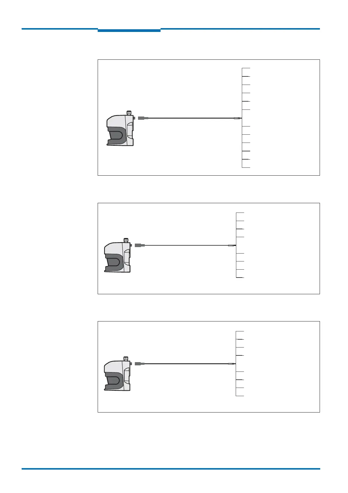
LMS511 PRO/LMS581 PRO Security/LMS511 Heavy Duty: “I/O” connection
Fig. 49: LMS511 PRO/LMS581 PRO Security/LMS511 Heavy Duty: “I/O” connection
LMS531 Lite Security: “Inputs” connection
Fig. 50: LMS531 Lite Security: “Inputs” connection
LMS531 Lite Security: “Alarm” connection
Fig. 51: LMS531 Lite Security: “Alarm” connection
LMS511PRO/Heavy Duty
LMS581 PRO
Yellow = IN3
Green = GND IN3/4
Part no. 6042732, 5 m
Part no. 6042733, 10 m
Part no. 6042734, 20 m
Male connector
M12×12-pin
Black = GND OUT3 ... 6
White = IN1
Pink = IN2
Grey = IN4/IN Sync
Violet = OUT4
Red = OUT3
Blue = GND IN1/2
Brown = V
S
OUT 3 ... 6
Red+blue = OUT6/OUT Sync
Grey+pink = OUT5
LMS531 Lite
Security
Female connector
M12×8-pin
Part no. 6036153, 5 m
Part no. 6028420, 10 m
Part no. 6036154, 20 m
Yellow = Reserved
Green = Reserved
White = A/DA (IN1)
Pink =Reserved
Grey = Reserved
Red = GND IN
Blue = IN3
Brown = WT (IN2)
LMS531 Lite
Security
Male connector
M12×8-pin
Part no. 6036155, 5 m
Part no. 6036156, 10 m
Part no. 6036157, 20 m
Pink = Error B
Brown = Alarm B
Yellow = Alarm R B
Green = Alarm R A
White = Alarm A
Grey = Error A
Red = GND Sab
Blue = Sab
 Loading...


