Operating Instructions
LMS5xx
Electrical installation
8013796/ZM63/2017-05-09 © SICK AG · Germany · All rights reserved · Subject to change without notice 81
Chapter 6
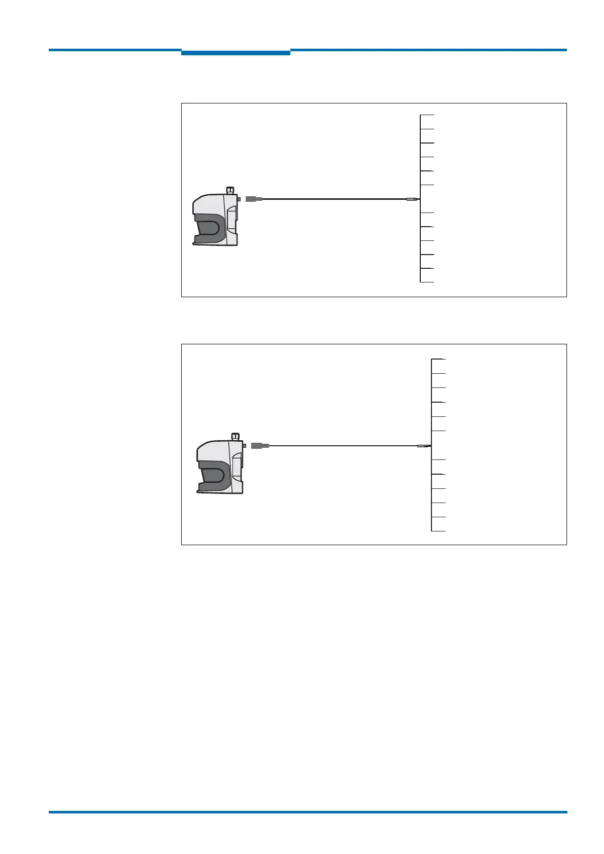
LMS531 PRO Security: “Inputs” connection
Fig. 52: LMS531 PRO Security: “Inputs” connection
LMS531 PRO Security: “Alarm” connection
Fig. 53: LMS531 PRO Security: “Alarm” connection“
LMS531 PRO
Security
Yellow = WT (IN2)
Brown = A/DA (IN1)
Part no. 6042735, 5 m
Part no. 6042736, 10 m
Part no. 6042737, 20 m
Dose
M12×12-polig
Grey = TEACH (IN4)
White = GND IN
Green = GND RS-422/232/CAN
Pink = D/N (IN3)
Red = RD+ (RS-422)
Blue = RD–/RxD (RS-422/232)
Black = TD–/TxD (RS-422/
232)
Violet = TD+ (RS-422)
Grey+pink = CAN-Bus low
Red+blue = CAN-Bus high
LMS531 PRO
Security
Yellow = Alarm R B
Green = Alarm R A
Part no. 6042732, 5 m
Part no. 6042733, 10 m
Part no. 6042734, 20 m
Stecker
M12×12-polig
Black = Disq. A
White = Alarm B
Pink = Error A
Grey = Error B
Violet = Disq. B
Red = Sab A
Blue = Sab A
Brown = Alarm A
Red+blue = Sab R B
Grey +pink = Sab R A
 Loading...


