Electrical installation
82 © SICK AG · Germany · All rights reserved · Subject to change without notice 8013796/ZM63/2017-05-09
Operating Instructions
LMS5xx Laser Measurement Sensors
Chapter 6
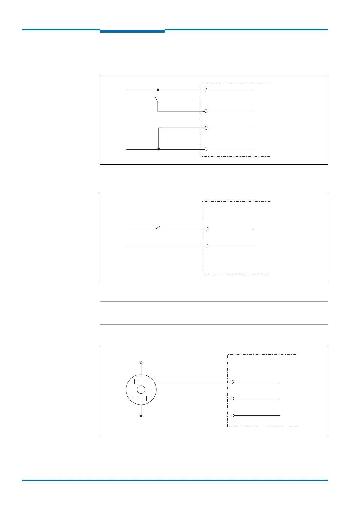
6.5.5 Wiring of inputs and outputs on the LMS5xx
Connecting digital inputs as non-floating
Fig. 54: Connecting digital inputs as non-floating
Connecting digital inputs as floating
Fig. 55: Connecting digital inputs as floating
Important The inputs require a switching voltage of at least 11 V. For this reason the supply voltage
must be at least 11 V.
Wiring encoder inputs (LMS5xx PRO/Heavy Duty only)
Fig. 56: Wiring encoder inputs
LMS5xx
IN1
GND IN1
GND
V
S
= DC 19.2 … 28.8 V
External switch
LMS5xx
IN1
GND IN1
External signal source
U
IN
= 11 V … 30 V
LMS5xx
INC1 IN3
INC2 IN4
GND
V
S
encoder
GND
0°
90°
 Loading...


