•
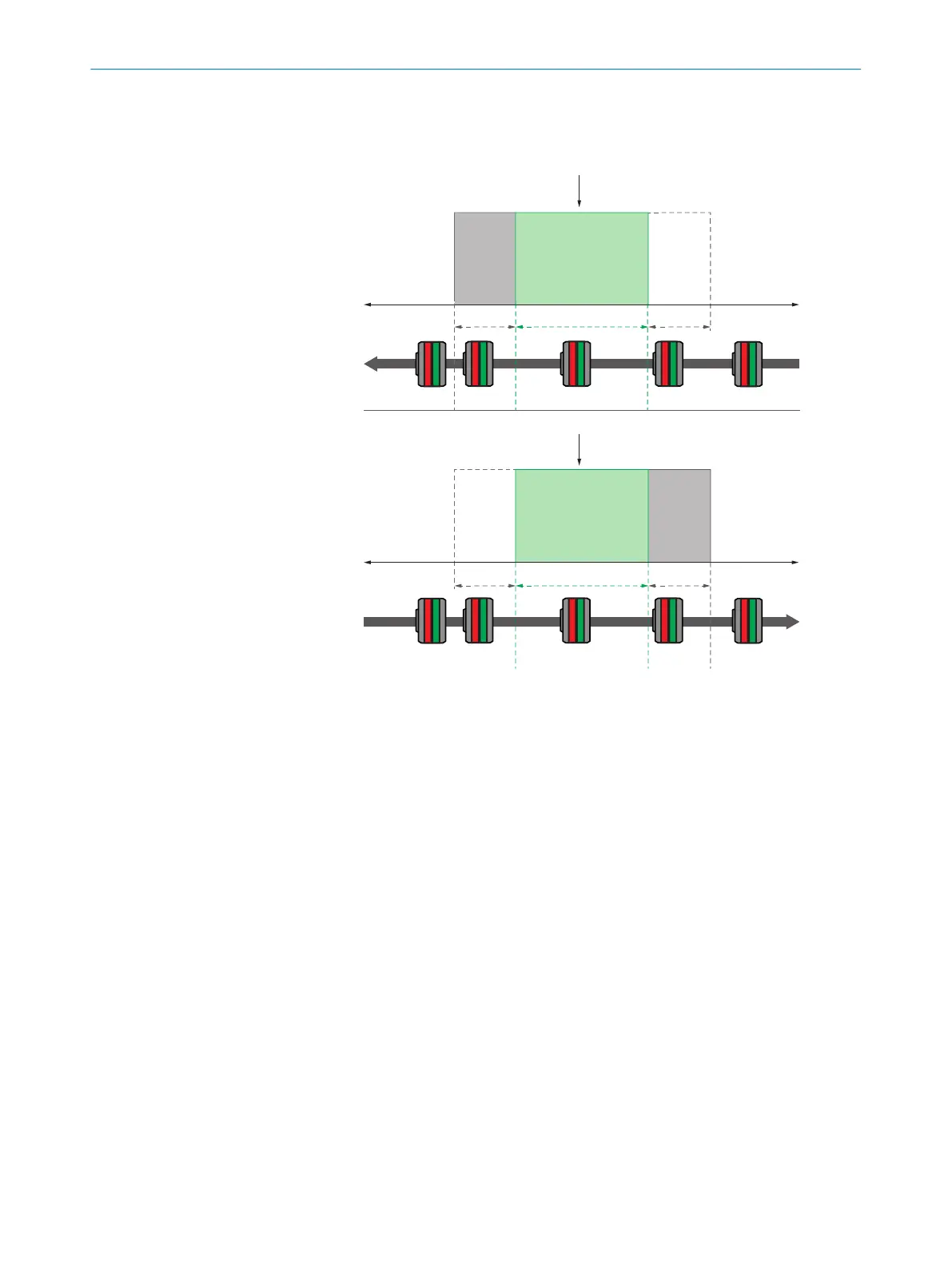
Cylinder switch mode: Within the width of the switching point, the switching signal is
high. The hysteresis is symmetrical around Qint.SP1.
Qint.SP1
+ 25 mm
OFF
ON
OFF
OFF
ON
OFF
+ 25 mm
– 25 mm
– 25 mm
ON ON OFF OFF
OFF OFF
ONON
Qint.SP1
2 1 2
2 1 2
3
3
1
Width of the switching point
2
Hysteresis
3
Direction of movement of the magnet
Depending on whether 2 or 3switching points are detected by the sensor during
dynamic teach-in, the sensor automatically selects Move mode (for 2 switching points)
or Grip mode (for 3 switching points). The two modes describe the switching behavior
after dynamic teach-in.
The switching behavior in Move mode is described in section 3.3.5 and the switching
behavior in Grip mode is described in section 3.3.6.
The Move and Grip modes are not available for manual teach-in. The 4 switching point
modes described above are not intended to be selected after performing a dynamic
teach-in.
8.4.3.8 Inverting the switchpoint logic
The logic of the taught-in switching points can be inverted using subindex 1 (0x01)
Switchpoint Logic. By default, the switching points are high in the case of an overrun.
8.4.3.9 Switching point hysteresis
After teaching in the switching point, the hysteresis is 0.7mm. The hysteresis can be
adjusted in 10 µmincrements via subindex 3 (0x03) Switchpoint Hysteresis (maximum
hysteresis: 327.67mm and minimum hysteresis: 0.01mm).
OPERATION 8
8028195/2022-11-30 | SICK O P E R A T I N G I N S T R U C T I O N S | MPS-G with 2/3 switching points and IO-Link (up to 8 switching points)
43
Subject to change without notice