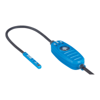
The negative direction goes in the direction of the sensor cable. One stroke corre‐
sponds to movement in a direction. Direction of movement during retraction: Start
position - stop position. The start position is in the direction of the sensor cable. The
stop position is in the direction of the top of the sensor head.
8.4.4.5 Average piston velocity during extension and retraction (Average actuator velocity)
The average velocity in m/s of the piston in the positive direction (extension of the
piston) can be read via index 4375 (0x1117) Average actuator velocity [m/s], subindex 1
(0x01) Extend (positive direction).
The average velocity in m/s of the piston in the negative direction (retraction of the
piston) can be read via index 4375 (0x1117) Average actuator velocity [m/s], subindex
2 (0x02) Retract (negative direction). The positive direction goes in the direction of the
sensor fixing screw. The negative direction goes in the direction of the sensor cable.
8.4.4.6 Current measured field strength at the sensor elements (Current field strength)
The current measured field strength for sensor element 1 in mT (Sensor element 1) and
sensor element 2 in mT (Sensor element 2) can be read via index 4602 (0x11FA) Current
field strength [mT], subindex 1 (0x01) Current1 and subindex 2 (0x02) Current2. Sensor
element 1 is in the direction of the cable of the sensor and sensor element 2 is in the
direction of the fixing screw of the sensor.
8.4.4.7 Maximum measured field strength at the sensor elements (Peak field strength)
The maximum measured field strength for sensor element 1 in mT (Sensor element 1)
and sensor element 2 in mT (Sensor element 2 ) since the last Power cycle can be read via
index 4604 (0x11FC) Peak field strength [mT], subindex 1 (0x01) Current1 and subindex
2 (0x02) Current2. Sensor element 1 is in the direction of the cable of the sensor and
sensor element 2 is in the direction of the fixing screw of the sensor.
8.4.4.8 Cycle count
The number of cycles can be read via index 4382 (0x111E) Cycle count [sum]. One cycle
corresponds to 2 strokes: start position - stop position - start position.
The start position is in the direction of the sensor cable. The stop position is in the
direction of the sensor fixing screw.
The number of cycles is only stored in the EEPROM every 100cycles. If the voltage
supply is interrupted after 99cycles, 0cycles are read again via IO-Link after the
voltage cycle. (This solution was chosen so that the EEPROM is not written to too often
in order to ensure a long service life)
8.4.4.9 Total distance traveled by the piston (Total actuator travel)
The total distance traveled by the piston in m can be read via index 4374 (0x1116)
Total actuator travel [sum m]. The total distance traveled by the piston is only stored in the
EEPROM every 10m.
If the voltage supply is interrupted after a travel distance of 9.99m, 0.0m is read again
via IO-Link after the voltage cycle.
8.4.4.10 Operating hours
The operating hours in h is output via the index 4356 (0x1104) Operating hours. This
index has three sub-indices, which corresponds to 3 different counters.
The first counts the absolute operating hours (1 (0x01) Total). The second counts the
operating hours since the last reset (2 (0x02) Since last reset), and the third counts the
time since the last Power-on (3 (0x03) Since startup).
8 OPERATION
46
O P E R A T I N G I N S T R U C T I O N S | MPS-G with 2/3 switching points and IO-Link (up to 8 switching points) 8028195/2022-11-30 | SICK
Subject to change without notice
 Loading...


