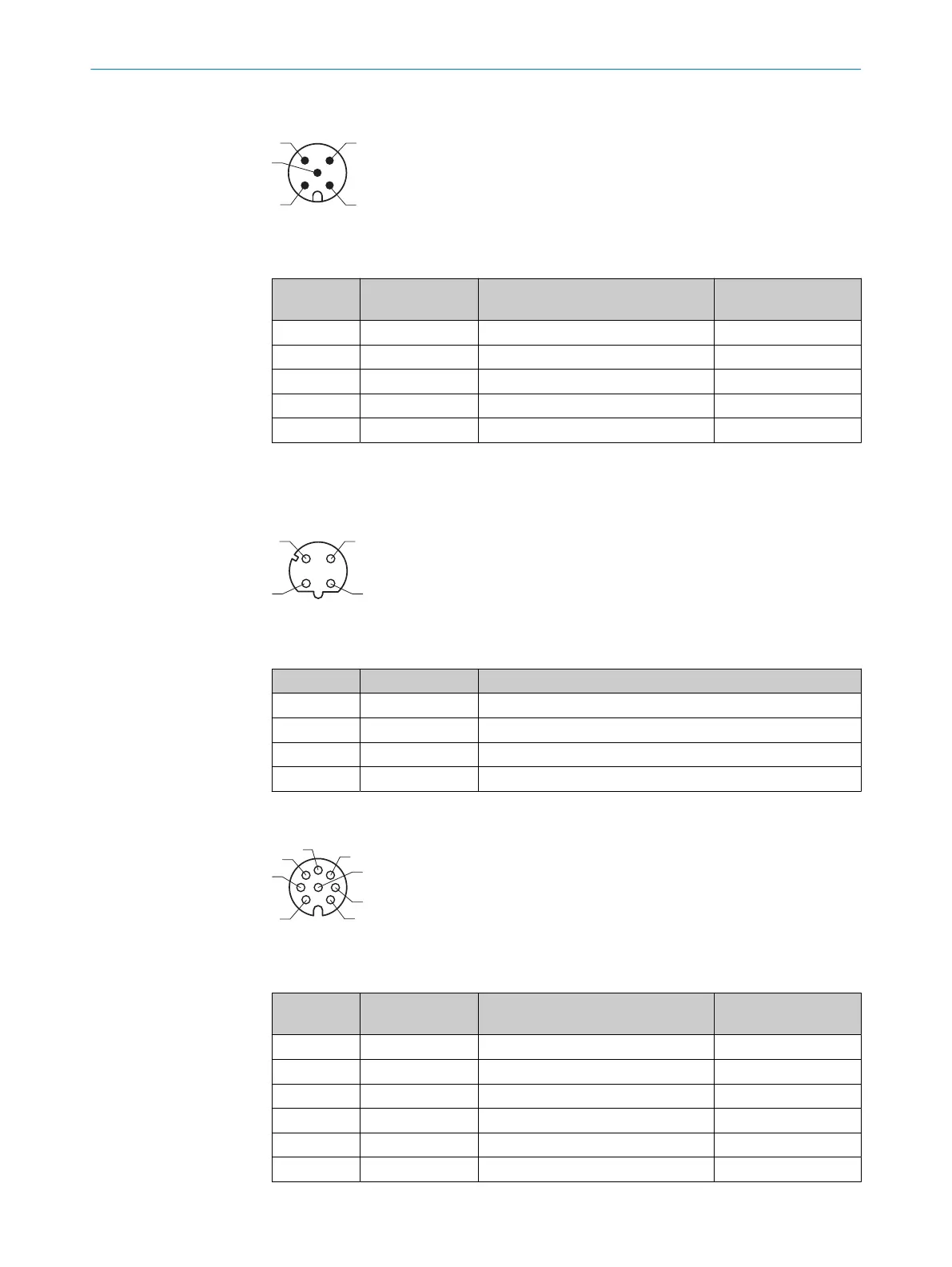
PWR connection
Figure 36: Male connector M12, 5-pin, A-coded
Table 9: Pin assignment for PWR connection
Pin Identification Description Wire color, part num‐
ber 2095733
1
1 Vs Supply voltage: +10 ... +30 V DC Brown
2 - Reserved White
3 GND Supply voltage: 0 V Blue
4 IN8 / OUT8 Digital input 8 / digital output 8 Black
5 - Reserved Gray
1
Information only valid when using the specified open-ended connecting cable which is available as an
accessory
Ethernet connection
Figure 37: M12 female connector, 4-pin, D-coded
Table 10: Pin assignment for Ethernet connection
Pin Identification Description
1 TX+ Sender+
2 RX+ Receiver+
3 TX- Sender-
4 RX- Receiver-
I/O connection
Figure 38: Female connector, M12, 8-pin, A-coded
Table 11: Pin assignment for I/O connection
Pin Identification Description Wire color, part num‐
ber 6036155
1
1 IN1 / OUT1 Digital input 1 / digital output 1 White
2 IN2 / OUT2 Digital input 2 / digital output 2 Brown
3 IN3 / OUT3 Digital input 3 / digital output 3 Green
4 IN4 / OUT4 Digital input 4 / digital output 4 Yellow
5 IN5 / OUT5 Digital input 5 / digital output 5 Gray
6 IN6 / OUT6 Digital input 6 / digital output 6 Pink
6 ELECTRICAL INSTALLATION
40
O P E R A T I N G I N S T R U C T I O N S | MRS1000 8020494/1AZF/2021-05-10 | SICK
Subject to change without notice