4
3
2
1
2,5°
2,5°
2,5°
Height in m (ft)
1
(
3.28
)
2
(
6.56
)
3
(
9.84
)
4
(
13.12
)
5
(
16.41
)
6
(19.69)
–1
(–
3.28
)
–2
(–
6.56
)
–3
(–
9.84
)
0
0
Radius in m (ft)
20
(65.62)
40
(131.24)
60
(
196.86
)
80
(
262.48
)
Max. scanning range
10 % Remission
90 % Remission
1
2
3
4
Layer 4
Layer 3
Layer 2
Layer 1
Typical
scanning range
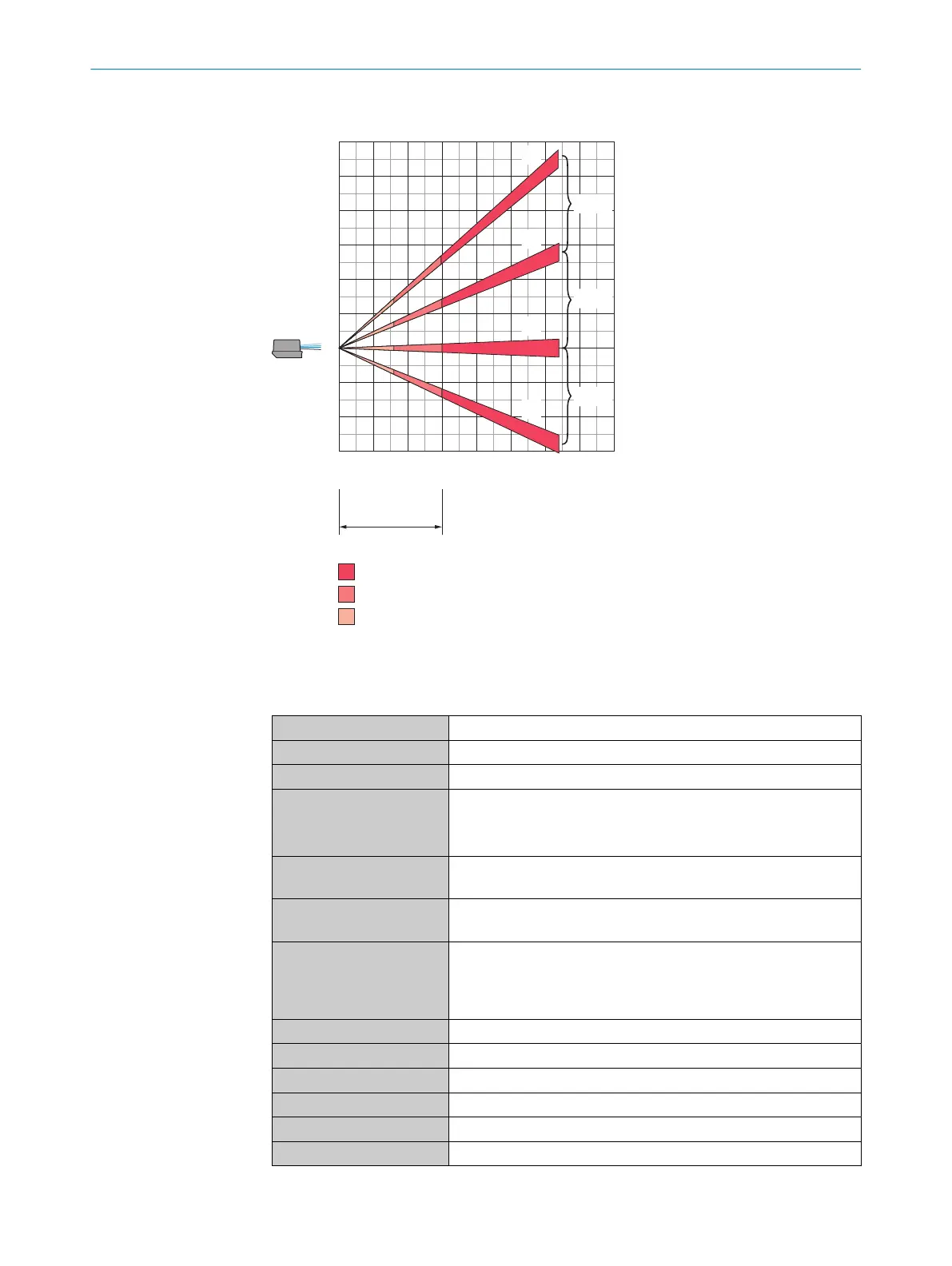
Figure 43: Working area diagram, side view
10.2
Mechanics/electronics
Connection type 3 x M12 round connectors with swivel connector
Supply voltage 10 V DC ... 30 V DC
Permissible residual ripple ±5%
Power consumption P
typ
= 13 W
P
start
= 30 W for 1 s (motor start-up)
P
max
= 37 W (with full specified current at all outputs)
Housing ALSi12
Optics cover: PC
Housing color MRSxxxxx-xxxxx0: Light blue(RAL 5012)
MRSxxxxx-xxxxx1: Gray (RAL 7042)
Enclosure rating MRSxxxxx-0xxxxx (indoor): IP65 (IEC
60529:1989+AMD1:1999+AMD2:2013)
MRSxxxxx-1xxxxx (outdoor): IP65 / IP67 (IEC
60529:1989+AMD1:1999+AMD2:2013)
Protection class III (IEC 61140:2016-11)
Electrical safety IEC 61010-1:2010-06
Weight 1.2 kg
Dimensions (L x W x H) 151.9 mm x 150 mm x 92.5 mm
Encoder input frequency not available
Maximum output current max. 100 mA per output
1)
e.g., 30 V*100 mA = 3 W
TECHNICAL DATA 10
8020494/1AZF/2021-05-10 | SICK O P E R A T I N G I N S T R U C T I O N S | MRS1000
53
Subject to change without notice