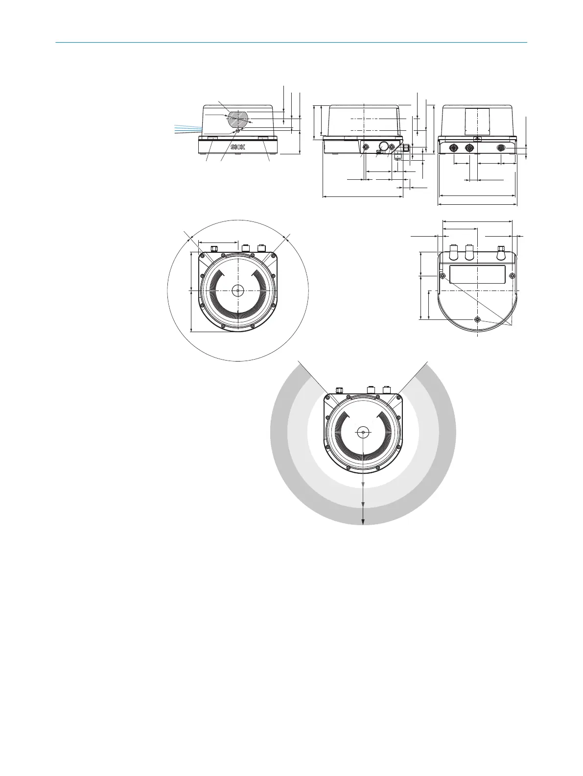
10.3 Dimensional drawing
22 (0.87)
1
4
13 (0.51)
43.8
(1.72)
16 (0.63)
+5°
+2.5°
–2.5°
0°
2
11.2 (0.44)
30
(1.18)
45
(1.77)
15 (0.59)
144 (5.67)
150 (5.22)
132.6 (5.22)
66.3 (2.61)
45.6
(1.80)
82.9 (3.26)
55 (2.17)
8.7(0.34)
85°
7
73.5 (2.89)78.4 (3.09)
75 (2.95)
275°
8
3
3
9
à
á
ß
Ø 37.9
(1.49)
8.7(0.34)
30
(1.18)
0.2 … 0.4
(7.87 … 15.75)
< 0.2
(7.87)
< 0.4
(15.75)
â
ã
ä
0
Ø 7 (0.28)
92.6 (3.65)
22 (0.87)
30.7 (1.21)
151.9 (5.98)
49 (1.93)
21
(0.83)
3.5
(0.14)
13.8
(0.54)
9.6
(0.38)
12.1
(0.48)
13.2 (0.52)
5
5
6
58.5
(2.30)
65.1 (2.56)
Figure 44: MRS1000 device structure and dimensions, dimensions in mm
1
Receiver
2
Laser aperture angle, layers 1 to 4
3
Status LEDs
4
Sender
5
M5x7.5 fixing holes
6
Pressure compensation element
7
Blind spot
8
Field of view
9
Ethernet connection
ß
I/O connection
à
PWR connection (supply voltage)
á
M5x7.5 fixing holes
â
Close range (no detection or measurement possible)
10 TECHNICAL DATA
54
O P E R A T I N G I N S T R U C T I O N S | MRS1000 8020494/1AZF/2021-05-10 | SICK
Subject to change without notice