2
Feedback LED
3
Opening in the illumination for the aiming laser
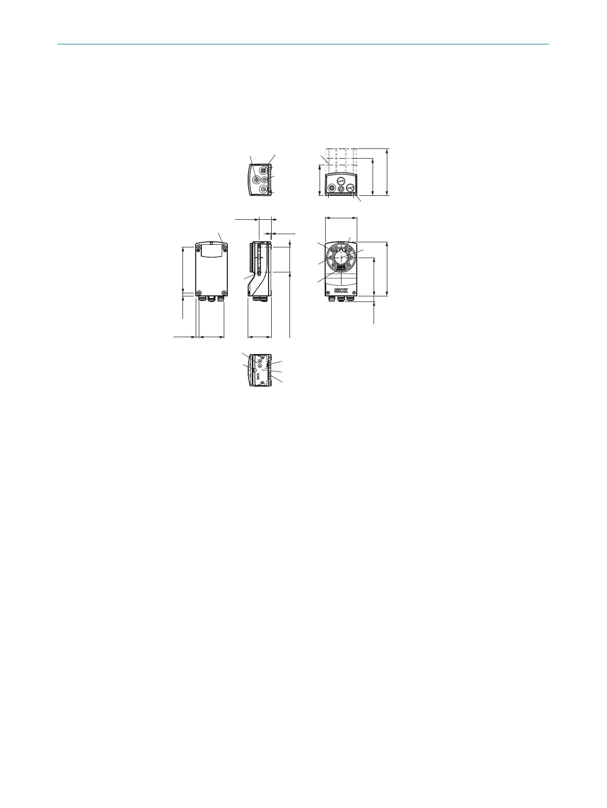
3.4.2 Device view (InspectorP63x)
Dimensional drawing ofInspectorP63x devices
59.1
45.8
min. 8 – max. 50
91.8
5.9
6.5 50
23.9
0.5
74.1
63.1
76.6
108
10.8
1 2
3
4
5
6
7
8
9
ä
å
æ
ç
ã
ß
à
á
â
96.4
1
External illumination connection
2
Gigabit Ethernet port
3
USB port, not used
4
Power, serial, CAN, and I/O connection
5
22.7mm, 37.7mm, or 60mm protective optics cover
6
Protective caps/plugs to seal any electrical connections that are not in use
7
M5 blind tapped holes, 5.5mm deep (4 x), for mounting the sensor
8
M5 sliding nut, 5.5mm deep (4 x), pivoting, for an alternative method of mounting the
sensor
9
Internal illumination connection
ß
Aiming laser (2 x)
à
S-mount or C-mount optics module
á
2.5mm blind tapped holes (4 x) for mounting the spacers for the integrable illumination
â
Optical axis and center of the image sensor
ã
Manual focus screw, underneath cover/label (S-mount)
ä
Function button (2 x)
å
LED bar graph (5 x)
æ
Removable cover for microSD card and manual focus screw (S-mount)
ç
LEDs for status display (5 x2 levels)
PRODUCT DESCRIPTION 3
8020736/1K3Z/2023-06 | SICK O P E R A T I N G I N S T R U C T I O N S | PLOC2D 4.1
13
Subject to change without notice