Pin Power and I/O Ethernet, 8-pin Ethernet, 4-pin External illumination
6 TD– (RS-422), Host
TxD (RS-232), Host
TRD3_N ‒ ‒
7 TxD (RS-232), Aux TRD2_P ‒ ‒
8 RxD (RS-232), Aux TRD2_N ‒ ‒
9 SensGND ‒ ‒ ‒
10 Sensor 1 switching input ‒ ‒ ‒
11 RD+ (RS-422), Host ‒ ‒ ‒
12 RD– (RS-422), Host
RxD (RS-232), Host
‒ ‒ ‒
13 Out1 ‒ ‒ ‒
14 External illumination output ‒ ‒ ‒
15 In2 ‒ ‒ ‒
16 Conveyor tracking output ‒ ‒ ‒
17 Out4 ‒ ‒ ‒
6.3 Connecting the device
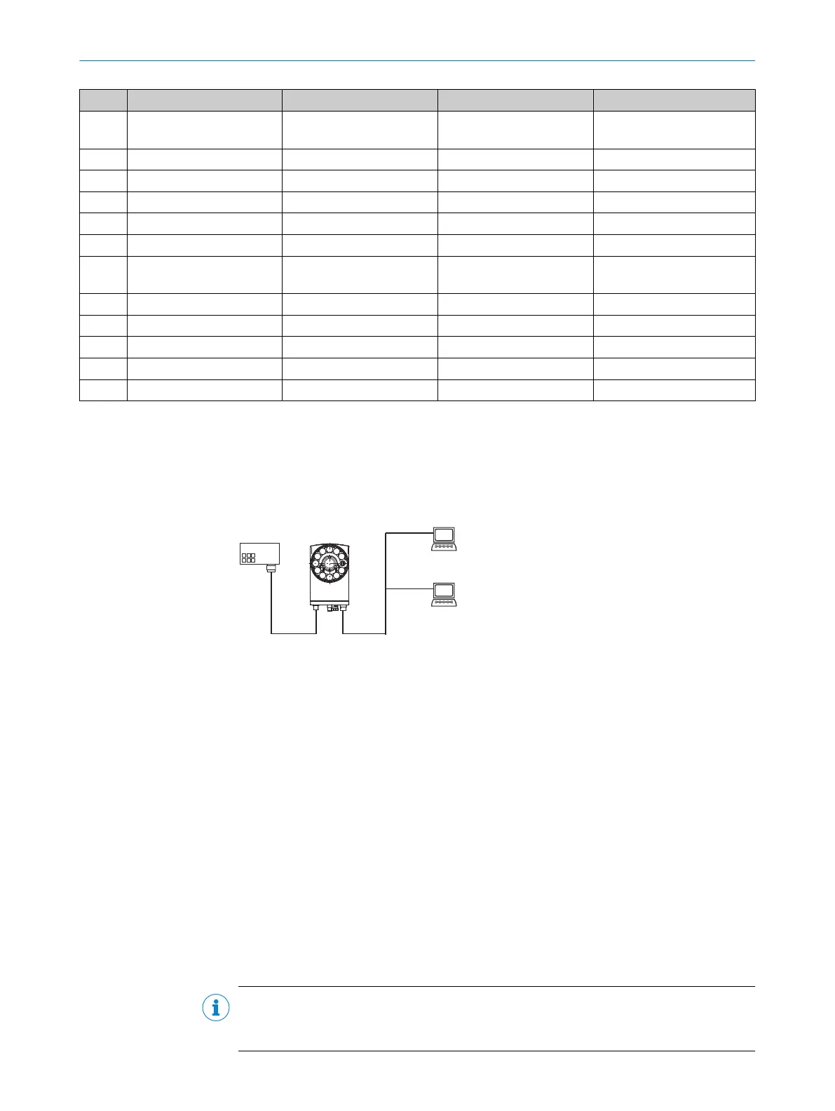
6.3.1 Connection diagram
Connection principle
Connection module
e.g. CDB650-205
no. 1064114
Web UIWeb UI
Configuration
Image display
Diagnostics
Power I/O Ethernet
Power cable
e.g. 6051195
Ethernet cable
e.g. 2106259 (X-coded)
or 2106184 (D-coded)
...
...
PLOC2D
Robot
controller
Robot
controller
Robot
communication
Figure 11: General connection principle
When PLOC2D is used with a CDB650 connection module, connect External illumination
trigger output (pin 14) to terminal 21 and Conveyor tracking output (pin 16) to terminal 50.
Wiring without a SICK connection module
For use with a custom connection unit, see "Connectors and pin assignment", page 33.
6.3.2 Wiring the data interface
Wiring the Ethernet interface
To connect the sensor to the PC:
1. Connect the sensor to the PC via Ethernet.
To connect the sensor to the PC and the robot controller:
1. Connect the sensor to a network switch by an Ethernet cable.
2. Connect the network switch to the PC via Ethernet.
3. Connect the network switch to the robot controller via Ethernet.
NOTE
The Ethernet interface for the device has an Auto-MDIX function. This automatically
adjusts the transmission speed as well as any necessary crossover connections.
ELECTRICAL INSTALLATION 6
8020736/1K3Z/2023-06 | SICK O P E R A T I N G I N S T R U C T I O N S | PLOC2D 4.1
35
Subject to change without notice