3
USB (not used)
4
Ethernet, 8-pin
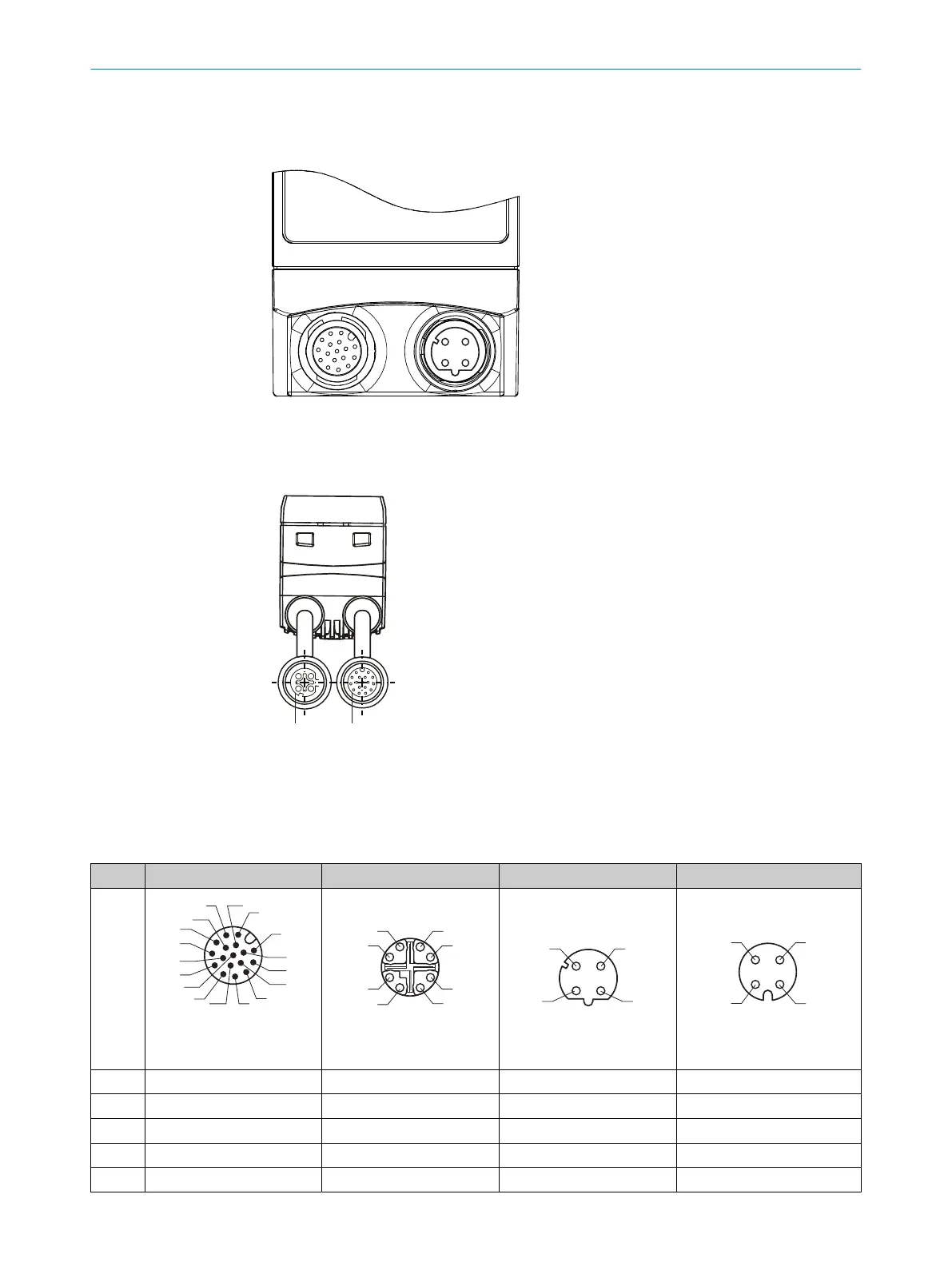
Figure 9: InspectorP62x connectors
1
Power and I/O
2
Ethernet, 4-pin
Figure 10: InspectorP611 connectors
1
Ethernet, 4-pin
2
Power and I/O
Pin assignments
Pin Power and I/O Ethernet, 8-pin Ethernet, 4-pin External illumination
3
1
7
2
6
5
4
8
13
14
17
15
9
10
12
16
11
17-pin M12 male
connector, A-coded
8-pin M12 female
connector, X-coded
4-pin M12 female
connector, D-coded
4-pin M12 female
connector, A-coded
1 GND TRD0_P TD+ DC 24 V switchable output
2 DC 24 V ± 20% TRD0_N RD+ Trigger illumination DC 24 V
3 CAN L TRD1_P TD– GND
4 CAN H TRD1_N RD– Not connected
5 TD+ (RS-422), Host TRD3_P ‒ ‒
6 ELECTRICAL INSTALLATION
34
O P E R A T I N G I N S T R U C T I O N S | PLOC2D 4.1 8020736/1K3Z/2023-06 | SICK
Subject to change without notice