6.1.2 Wiring notes
NOTICE
Faults due to incorrect wiring.
Incorrect wiring may result in operational faults.
■
For data transmission, use only screened cables with twisted-pair wires.
■
Follow the wiring notes precisely.
NOTE
Preassembled cables can be found online at:
►
www.sick.com
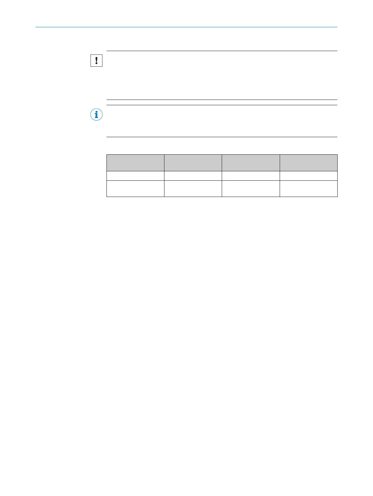
Power supply wiring requirements
Connector
1)
Max. fuse protection Min. recommended
cross-section
2)
Electromagnetic com‐
patibility
A-coded 4 A 0.34 mm
2
Use shielded cable
L-coded 16 A 1.5 mm
2
Connect Functional
earth wire
All electrical connections of the device are configured as round connectors. The IP65
protection class is only achieved with screwed plug connectors or cover caps.
Please observe the following wiring notes:
■
A correct and complete cable shielding design is required for trouble-free data
transmission.
■
The cable shield must be connected at both ends in the electrical enclosure and
at the device.
■
The cable shield in the control cabinet must be connected to a large area of the
signal ground, see figure 5, page 31).
■
Appropriate measures must be taken to prevent equipotential bonding currents
flowing through the cable shield.
■
During installation, pay attention to the different cable groups. The cables are
grouped into the following 4 groups according to their sensitivity to interference or
radiated emissions.
°
Group 1: Cables very sensitive to interference, such as analog measuring
cables
°
Group 2: Cables sensitive to interference, such as sensor cables, communi‐
cation signals, bus signals
°
Group 3: Cables which are a source of interference, such as control cables
for inductive loads, motor brakes
°
Group 4: Cables which are powerful sources of interference, such as out‐
put cables from frequency inverters, welding system power supplies, power
cables
►
Cables in groups 1, 2, and 3, 4 must be crossed at right angles see figure 2,
page 30
►
Cables in groups 1, 2, and 3, 4 must be routed in different cable channels or
metallic separators must be used, see figure 3, page 30 and see figure 4,
page 30. This applies particularly where cables of devices with a high level
of radiated emission, such as frequency converters, are laid parallel to
sensor cables.
1)
see "Connectors and pin assignment", page 33
2)
The supply cable from the power system must be designed in accordance with the applicable standards.
ELECTRICAL INSTALLATION 6
8020736/1K3Z/2023-06 | SICK O P E R A T I N G I N S T R U C T I O N S | PLOC2D 4.1
29
Subject to change without notice