Mounting the illumination unit
NOTICE
Risk of damage due to electrostatic discharge!
Electrostatic discharge from the human body may damage parts of the illumination unit
or the camera housing.
The illumination variants for lenses with a focal distance of 12 mm or 16 mm do not
feature any plastic lenses in front of the LEDs in the round recesses.
►
Do not insert your fingers into the recesses.
►
Do not touch the open contacts of the electrical connection for the illumination
unit on the camera housing.
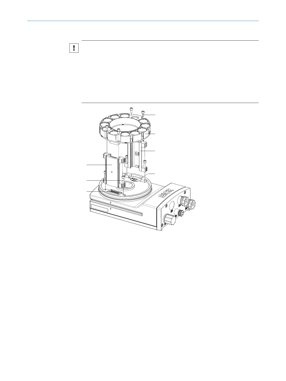
1
2
3
4
5
6
7
1 Spacer, left with
electrical connection
2 Long screw (4 x)
3 Electrical connection
for ring light
4 Short screw (4 x)
5 Ring light
6 Spacer, right
7 Light inlet with
threaded connection
for lens
1. Peel off the white protective sticker on the camera housing that covers the electri‐
cal connection 3 for the illumination unit.
2. Take two pairs of long screws and screw them into the threaded mounting holes to
attach each spacer (1 and 6) to the correct side of the camera housing.
3.
Use the 4 short screws to attach the illumination unit 5 to the two spacers.
4. Manually preset the sharpness and aperture of the lens unit.
5. Mount the optics protective hood.
MOUNTING
5
8020736/1K3Z/2023-06 | SICK O P E R A T I N G I N S T R U C T I O N S | PLOC2D 4.1
27
Subject to change without notice