7 Operation
7.1 Configuration options
The complete configuration of the SLG-2 is possible via the IO-Link interface. Using the
SiLink2 master and the SOPAS ET configuration software, the SLG-2 can be configured
directly on the computer.
For configuration via SOPAS ET, the sensor-specific SOPAS Device Description (SDD) is
required.
Both SOPAS ET and the SOPAS Device Description can be downloaded free of charge at
www.sick.com.
The interface-specific settings can be found at the end of the chapter, see "IO-Link
specific settings", page 42.
7.2
Functions structure
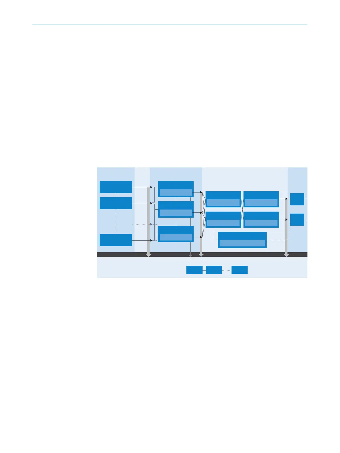
The graphic below describes the functional structure of the SLG-2.
Sensor Threshold
Teach-in
Beam
Status
Zones
Selection of beams & functions
Process Data
SmartTask A00
Selection of Q
ints
& logics
Pin
Beam
1
Selection of binary data: Q
int
, Q
L
Beam status, diagnosis data,
measurement values for basic functions
Beam
2
Beam
n
Zone 2 (beam x ... y)
Zone 4 (beam x ... y)
Zone 1 (beam x ... y)
Basic function 1
Input selector 1
Q
int
1 v Q
int
2 ... Q
int
4
Input selector 2
Q
int
1 v Q
int
2 ... Q
int
4
Pin 4
C/Q
L
1
Slot 1 Slot 2 Slot 32
Pin 2
MF
SmartTask function 1
Logic, timer, inverter
SmartTask function 2
Logic, timer, inverter
MF/Pin 2 configuration
Teach-in, BBH, logic input ...
Threshold beam 2
Basic function 2
Basic function 4
Basic function 1 ... 4
Threshold beam 1
Threshold beam n
Q
int
1
Q
L
1
Q
int
2
Q
int
4
Q
L
2
Figure 15: Function overview
In Sensor thresholds, the switching thresholds of all beams are automatically set via the
teach-in depending on the sensing range, see "Commissioning", page 23.
Beam status: After the teach-in, the SLG-2 is ready for operation. Now either the states
of each individual beam can be output via the process data (Process data) and/or the
sensor data can be used for further processing.
Zones: In Zones, ranges between two beams can be defined in which evaluation within
the zone is carried out by selectable functions. The resulting Q
int
signals can either
be used for further processing or output directly via the process data (Process data).
Furthermore, height and width information of an object within a defined zone can still
be output via the process data.
Smart Task:
two of the altogether four Q
int
signals (internal) can be further processed / adapted by
simple logic gates as well as by Timing and Inverter functions. Furthermore, an external
input signal can be integrated into the processing. The processed signals Q
L1
or Q
L2
can be output via pin 4 or pin 2 (Smart Task via IO-Link) and/or via the process data
(Process data).
OPERATION
7
8026014/2021-06-10 | SICK O P E R A T I N G I N S T R U C T I O N S | SLG-2
25
Subject to change without notice