7.7 Smart Task
Figure 26: SOPAS - Smart Tasks tab
Using the Smart Task tab, the states of the individual zones (Q
int
1 – Q
int
4) can be
processed further and thus simple evaluations / size comparisons can be carried out.
These Q
int
states as well as an external input signal are possible input variables which
are available for selection in the Input selector .
Via the settings for Logic 1/2, the input signal of Input selector 1 can be logically linked
with the input signal of Input selector 2 . OR and AND logic gates are available for this
purpose.
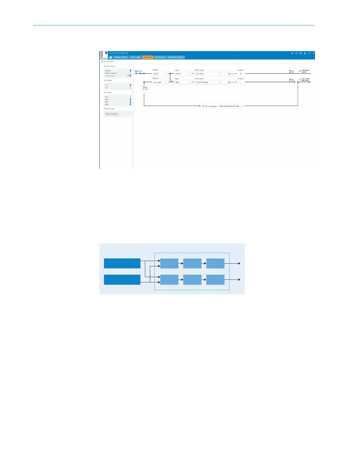
Input selector 1
A00
Q
L
1
Logic 1 Timer 1 Inverter 1
Input selector 2
Q
L
2
Logic 2 Timer 2 Inverter 2
Figure 27: Logical principle of operation of the Smart Task function
Various delay modes can be selected via Timer 1/2 mode . The associated delay time is
set via Time 1/2 setup . See the graph below for details on how the various modes work.
OPERATION
7
8026014/2021-06-10 | SICK O P E R A T I N G I N S T R U C T I O N S | SLG-2
35
Subject to change without notice