5.2 Pin assignment of the connections
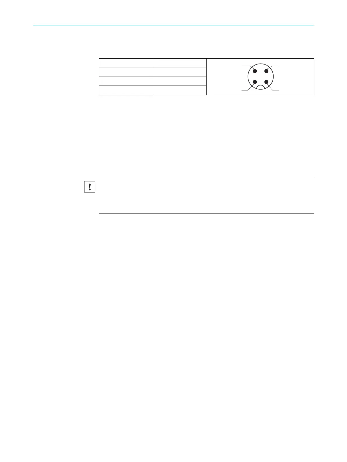
Table 2: Pin assignment
1 = BN + (L+)
2 = WH MF
3 = BU - (M)
4 = BK
Q
L1
/ C
The Q
L1
/ C (pin 4) and MF (pin 2) interfaces can be configured via the SOPAS engineer‐
ing tool (in conjunction with the SI-LINK2 master (SICK part number: 1061790)) or
directly via the IO-Link interface. MF (pin 2) can be configured as input or as output. Q
L1
can only be configured as an output. Each digital interface can be assigned different
functions, chapter 7.7.
Pre-configured device variants are available (see www.sick.com/SLG-2).
5.3 Connecting the supply voltage
Only connect the sensors when the supply cable is de-energized.
NOTICE
Risk of damage to sensors
The sensors can become damaged if they are connected to a voltage supply that is
already switched on.
The sensors must be connected to a power supply unit with the following properties:
•
Supply voltage 18 ... 30 V DC (SELV/PELV as per currently valid standards)
•
The current consumption for the system consisting of sender and receiver is
between 100 mA and 420 mA, see "Technical data", page 51.
To ensure protection against short-circuits/overload in the customer’s supply cables,
the wire cross-sections used must be appropriately selected and protected.
5 ELECTRICAL INSTALLATION
22
O P E R A T I N G I N S T R U C T I O N S | SLG-2 8026014/2021-06-10 | SICK
Subject to change without notice