Chapter 3 Operating Instructions
UE403
14 © SICK AG • Industrial Safety Systems • Germany • All rights reserved 8010854/WP71/2012-11-28
Subject to change without notice
Product description
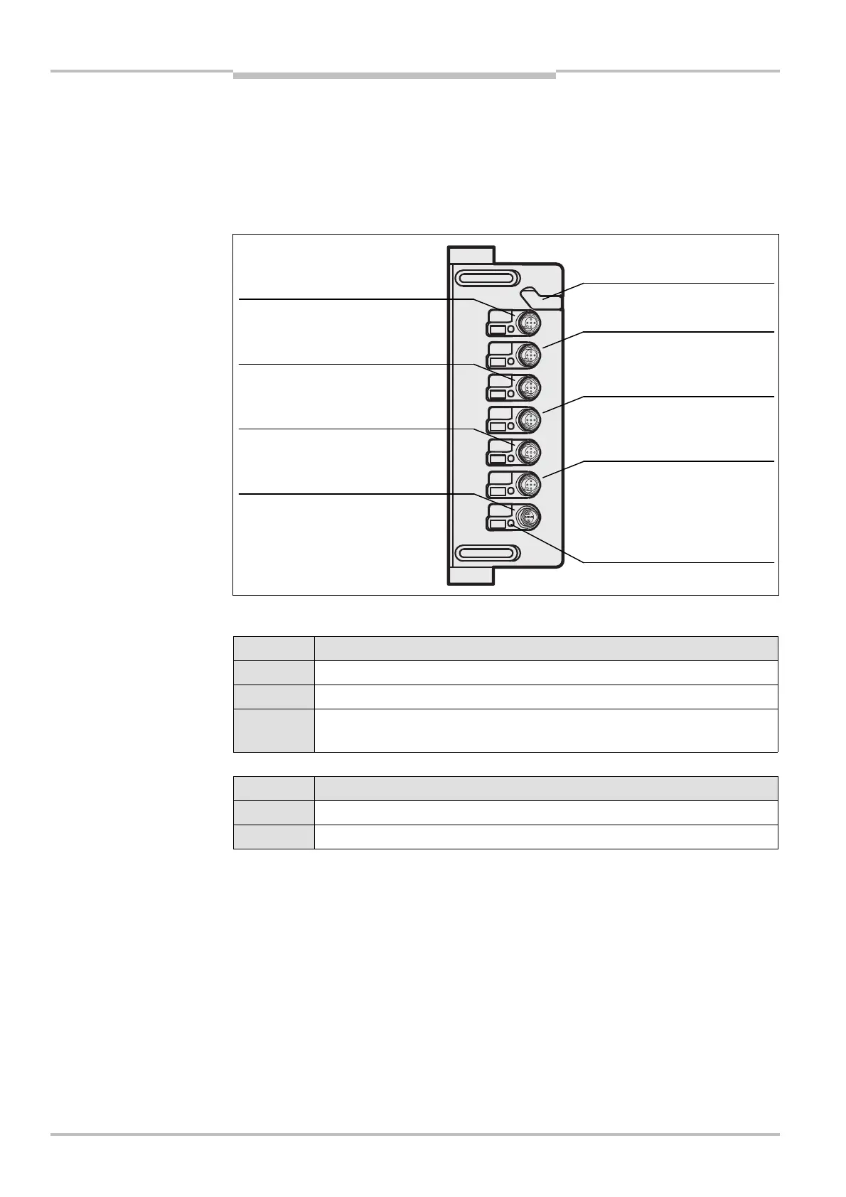
3.4 Status indicators
T
he UE403 has a status LED for the input and output (I/O) on each M12 connection. Other
indications during operation are also indicated on the 7>segment display on the M4000
receiver.
Status LED
COM connection
Display Meaning
Yellow LED off: No supply voltage
Yellow LED illuminated: Device ready for operation
Yellow LED flashing: Error
(See chapter 9.3 “Error displays of the LEDs” on page 30ff.)
Connections RES/OVR, A1, A2, B1, B2,
Display Meaning
Yellow LED off: No signal (0 V LOW)
Yellow LED illuminated: Signal is present (24 V HIGH)
• The combined RES/OVR connection can process several signals. However, the status
LED only indicates whether a signal is present or not. A decision as to which signal is
present is not made.
• The electrical connection is described in chapter 5.4 “Reset/override/additional signal
C1/belt stop connection M12× 5” on page 21.
Fig. 3: Status LED of the
UE403
LEDs of the UE403
Notes
RES/OVR:
Reset/override/C1/belt stop
Muting sensor
B2:
Muting sensor
COM:
EFI connection
A1:
Muting
B1:
Muting
:
External muting lamp
Configuration connection (
protective cover)