Chapter 5 Operating Instructions
UE403
22 © SICK AG • Industrial Safety Systems • Germany • All rights reserved 8010854/WP71/2012-11-28
Subject to change without notice
Electrical installation
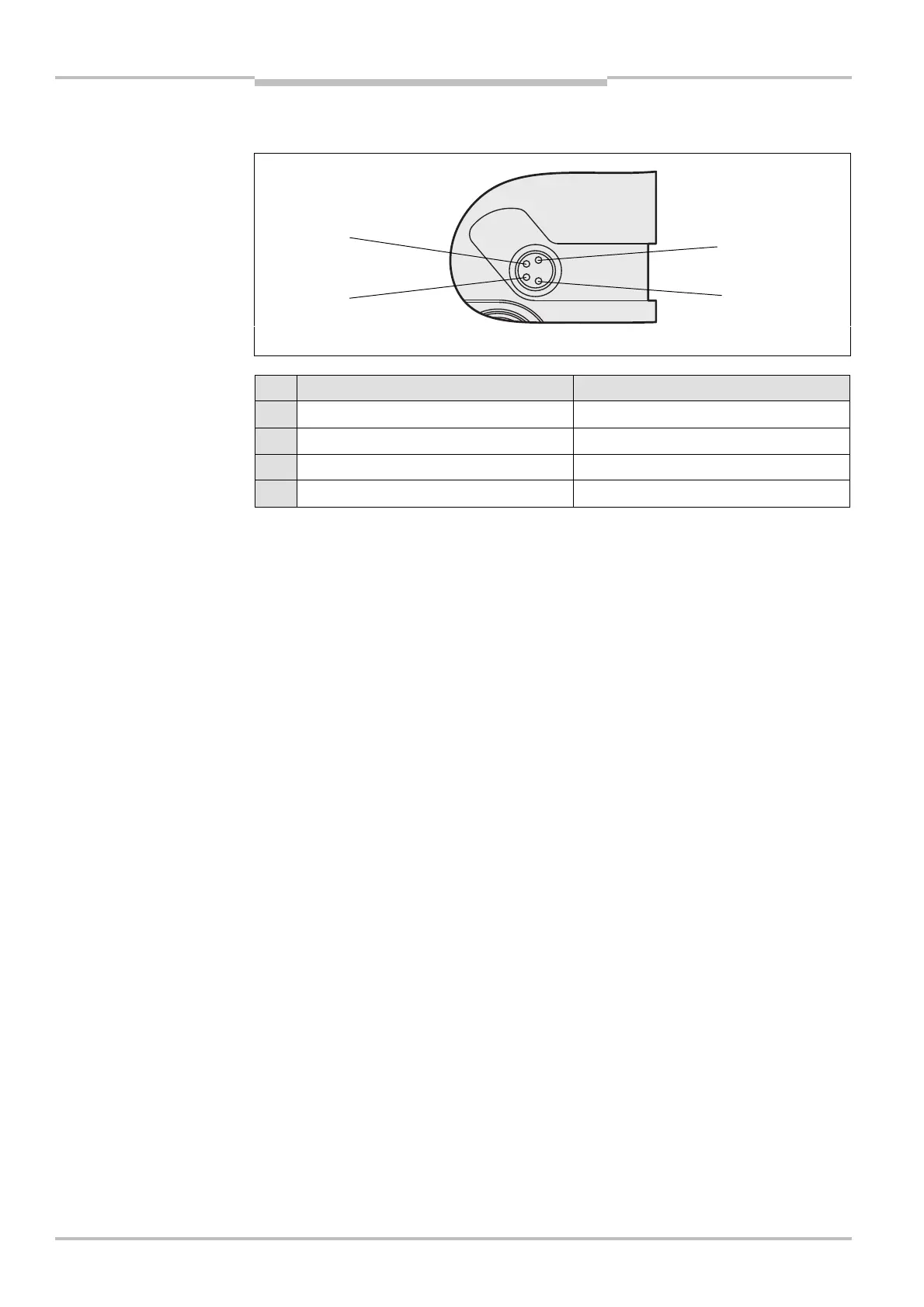
5.5 Configuration connection M8× 4 (serial interface)
Pin UE403 PC-side RSC232-DCSub (9-pin)
1 Not assigned –
2 RxD Pin 3
3 0 V DC (voltage supply) Pin 5
4 TxD Pin 2
After configuration always remove the connecting cable from the configuration
connection!
After the configuration of the device has been completed, locate the attached
protection cap to cover the configuration connection.
Fig. 10: Pin assignment
configuration connection
M8
× 4
configuration connection
M8
× 4
Notes