Operating Instructions Chapter 5
UE403
8010854/WP71/2012-11-28 © SICK AG • Industrial Safety Systems • Germany • All rights reserved 21
Subject to change without notice
Electrical installation
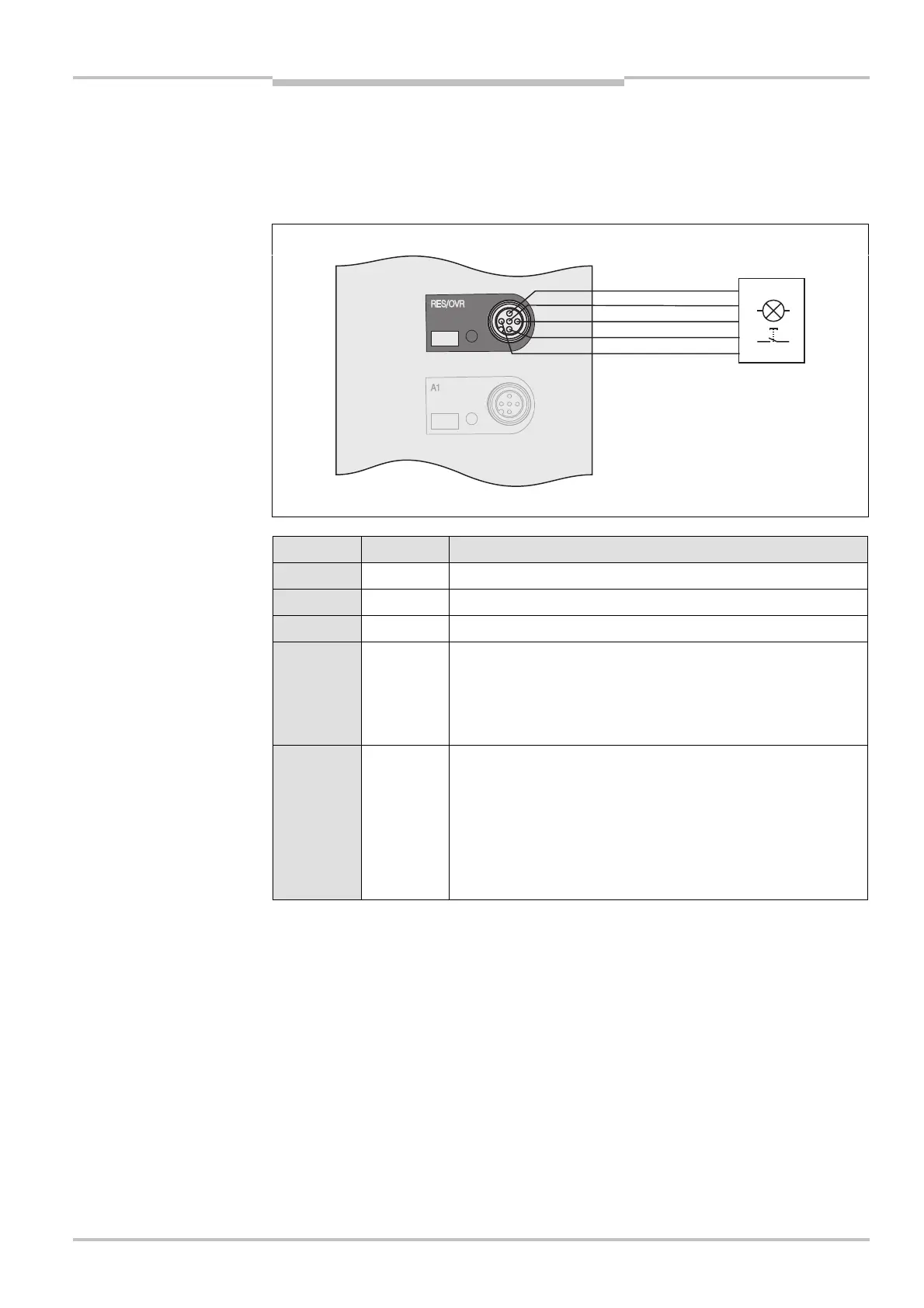
5.4 Reset/override/additional signal C1/belt stop
connection M12× 5
The UE403 switching amplifier has a combined connection for reset/override, for the
a
dditional signal C1 or for belt stop.
Pin Wire colour Description
1 Brown 24 V DC output (voltage supply)
2 White Output Reset required
3 Blue 0 V DC (voltage supply)
4 Black Input
• Reset/override (combined)
or
• Input reset
5 Grey Input
• Override
or
• Input additional signal C1
or
• Belt stop input
• The maximum cable length is 10 m.
• Connection cables are available as SICK accessories (see “Accessories” on page 36ff).
Fig. 9: Pin assignment
reset/override/additional
signal C1/belt stop M12
× 5
reset/override/additional
signal C1/belt stop M12
× 5
Notes