Operating Instructions Chapter 5
UE403
8010854/WP71/2012-11-28 © SICK AG • Industrial Safety Systems • Germany • All rights reserved 19
Subject to change without notice
Electrical installation
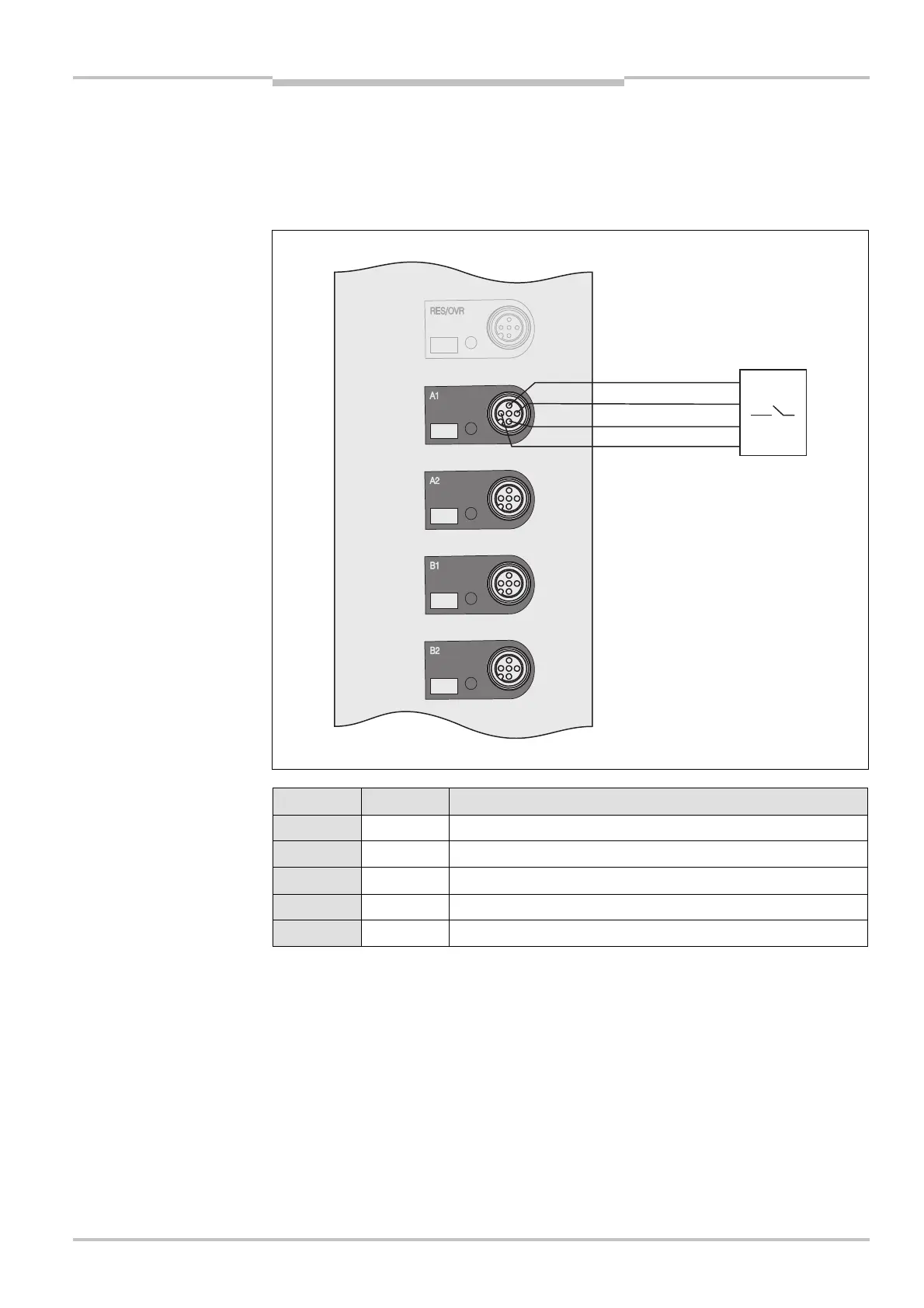
5.2 Connections for muting sensors M12× 5
T
he UE403 switching amplifier has four identical connections for muting sensors.
The inputs of the connections for muting sensors are compatible with the Type-1, Type>2
and Type>3 digital inputs described in DIN EN 61131>2.
Pin Wire colour Description
1 Brown 24 V DC output (voltage supply)
2 White Muting sensor test output
3 Blue 0 V DC (voltage supply)
4 Black Muting sensor input
5 Grey Reserved
• The maximum cable length is 10 m.
• Connection cables are available as SICK accessories (see “Accessories” on page 36ff).
Note
Fig. 7: Pin assignment for
muting sensors connection
M12
× 5
muting sensors connection
M12
× 5
Notes