64 / 92
Siemens Actuators SAX.., SAY.., SAV.., SAL.. for valves CE1P4040en
Building Technologies Functions and control 2018-12-05
4.8 Calibration
To match the actuator to production-related mechanical tolerances of the individual
valves, accurate positioning and position feedback must be ensured, if calibration
is performed when the plant is commissioned (page 46). During commissioning,
the actuator detects the valve’s end positions and files the exact stroke in its
internal memory.
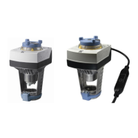
Calibration takes place in the following phases:
· Actuator drives to H
0
(1), valve closes. Detection
of upper end position.
· Actuator drives to H
100
(2), valve opens.
Detection of lower end position.
· The detected values are stored (3). Then the
actuator follows the positioning signal.
· Observe status indication (actuator LED) during and after calibration (page 74).
· If the actuator does not detect the second end position within an appropriate
stroke range (SAX.., SAY.. max. 25 mm; SAV.. max. 45 mm), the first end stop
will be adopted and the actuator operates with a working range of 20 mm,
respectively 40 mm.
4.9 Signal priorities
The actuators are controlled via different interlinked positioning signal paths
(positioning signal “Y“, forced control input “Z“, manual adjuster). The signal paths
are assigned the following priorities:
Priority Description
1
(highest)
The manual adjuster always has priority 1, thus overriding all signals active at
“Z“ or “Y“, independent of whether or not power is applied.
2
Only SA..61..: As soon as a valid positioning signal is active at input “Z“, the
position is determined via positioning signal “Z“ (forced control). Prerequisite:
The manual adjuster is not used.
Z
3
(lowest)
The position is determined via positioning signal ”Y”. The manual adjuster is
not used and on Z there is no active signal.
Y
Manual
adjuster
Forced
control (Z)
Positioning
signal (Y)
Stroke actuator Rotary actuator
Automatic
mode
Not
connected
5 V
Actuator’s stem travels to
position (50%)
Actuator’s spindle travels to
position (50%)
Automatic
mode
G 3 V Actuator’s stem extends
Actuator’s spindle turns in
clockwise direction
Automatic
mode
G0 3 V Actuator’s stem retracts
Actuator’s spindle turns in
counter-clockwise direction
Operated
(30%) and
engaged
G 8 V
Actuator’s stem retracts
manual (to 30%)
Actuator’s spindle turns
manual in counterclock-
wise direction (to 30%)
Bold printing = positioning signal currently active
Note
Examples
 Loading...


