82 / 92
Siemens Actuators SAX.., SAY.., SAV.., SAL.. for valves CE1P4040en
Building Technologies Connection diagrams and dimensions 2018-12-05
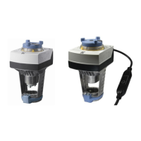
6.3 Connection diagrams
A Actuator
L Phase
N Neutral
N1 Controller
Y1, Y2 Positioning signals
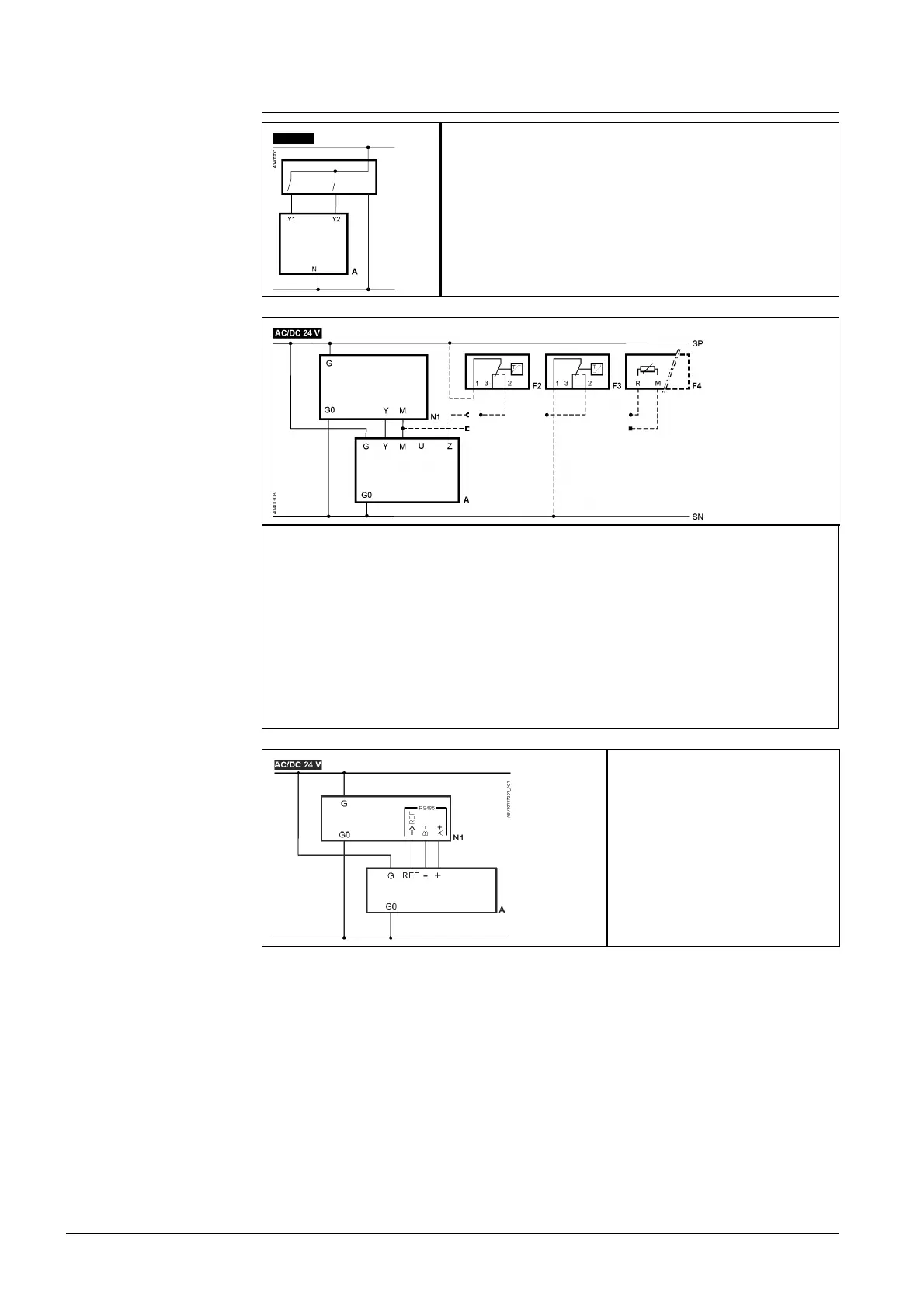
A Actuator
F2 Frost protection thermostat; terminals:
1 – 2 frost hazard / sensor is interrupted (thermostat closes with frost)
1 – 3 normal operation
F3 Temperature detector
F4 Frost protection monitor with 0…1000 Ω signal output, does NOT support QAF21.. or QAF61..
M Measuring neutral
N1 Controller
SN System neutral
SP System potential AC/DC 24 V
U Position feedback– (signal common is M)
Y Position signal
Z Positioning signal forced control
A Actuator
G0 System neutral (SN)
G System potential (SP)
N1 Controller
REF Reference (Modbus RTU)
+ Bus + (Modbus RTU)
- Bus - (Modbus RTU)
L
L
AC 230 V
SA..31..
SA..61..
SAX61../MO
 Loading...


