Industry Mobility
Betriebsanleitung PZENTW A6Z08101637795/EN1/000/B 10
[7620] ELP 319 LANGE_THO A25000-X22-Q9-7-7620 of
DC013 20081022 Notice no.: 500000097465 33
Copyright (C) Siemens AG 1998 All Rights Reserved - 0000ZQ6U.doc
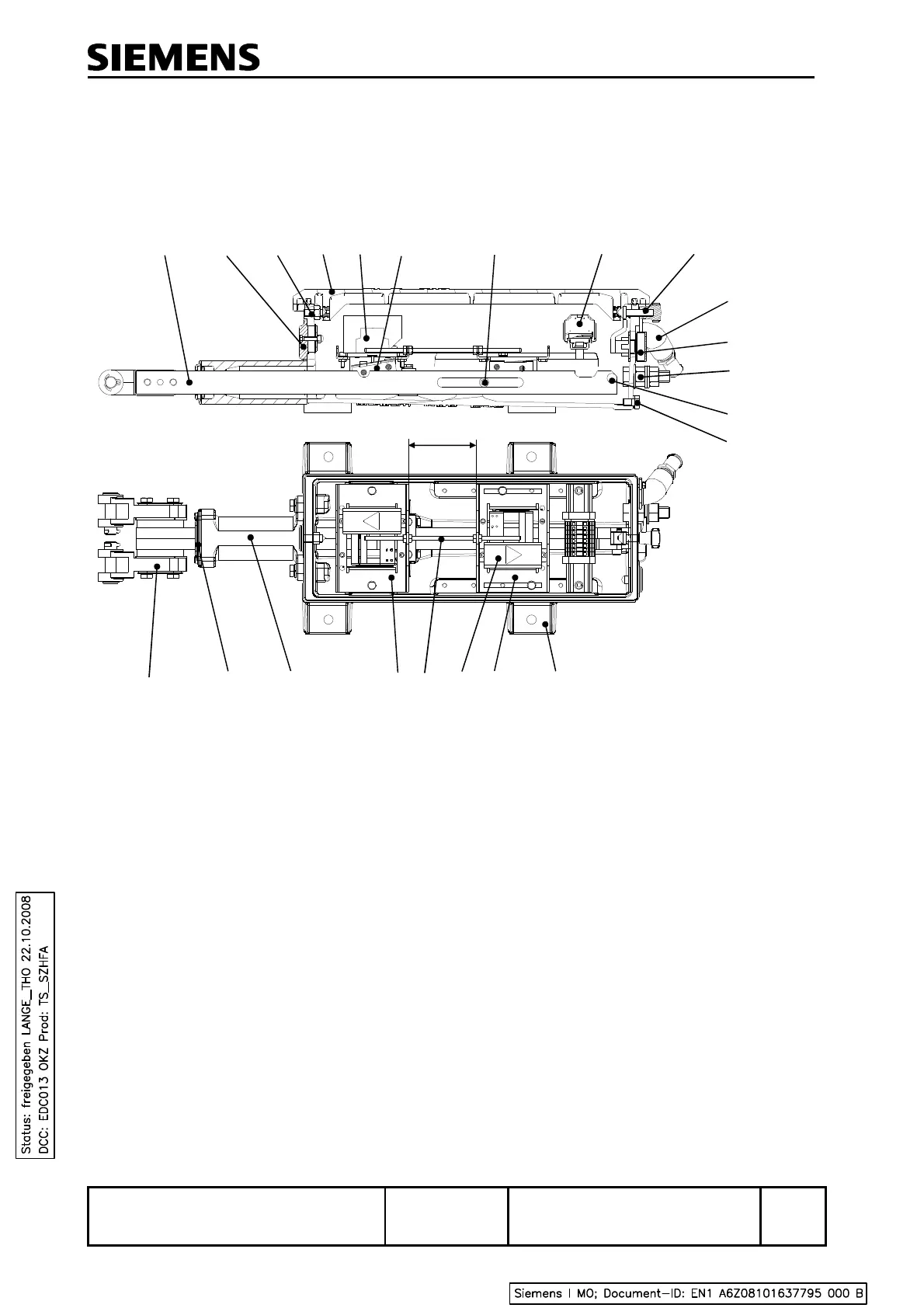
8.1 Components of the ELP 319 End Position Detector
The ELP 319 end position detector (see Figure 1) is of compact design and has only a few
components (see Figure 2). Its slide stroke can be continuously adjusted.
1 Housing 12 Cover
2 Movable contact arrangement 13 Limit switch
3 Set of contacts 14 Rocker
4 Threaded rod 15 Carrier
5 Fixed contact arrangement 16 Terminal strip
6 Guide sleeve 17 Tension screw (e.g. with star handle)
7 Gasket of slide 18 Cable gland
8 Insulated fork head 19 Built-in lock (if required)
9 Detector slides (with notches) 20 Earthing terminal
10
Ventilation opening 21 Stop pin
11
Adjusting screw 22 Drainage screw
Figure 2 Components of the ELP 319 end position detector
In the standard version, the housing cover is secured by a tension screw. In addition, a padlock or a
built-in lock can be provided.
The dimensions of the ELP 319 end position detector are shown in Figure 6.
 Loading...