Industry Mobility
Betriebsanleitung PZENTW A6Z08101637795/EN1/000/B 24
[7620] ELP 319 LANGE_THO A25000-X22-Q9-7-7620 of
DC013 20081022 Notice no.: 500000097465 33
Copyright (C) Siemens AG 1998 All Rights Reserved - 0000ZQ6U.doc
10.6 Individually Adjusting the Detector Slides
Depending on the type and layout of the equipment to be detected, the detector slide stroke of the
ELP 319 end position detector can be adjusted individually. The detection range of the ELP 319 end
position detector is adjusted to the respective point opening at the point of attachment of the detector
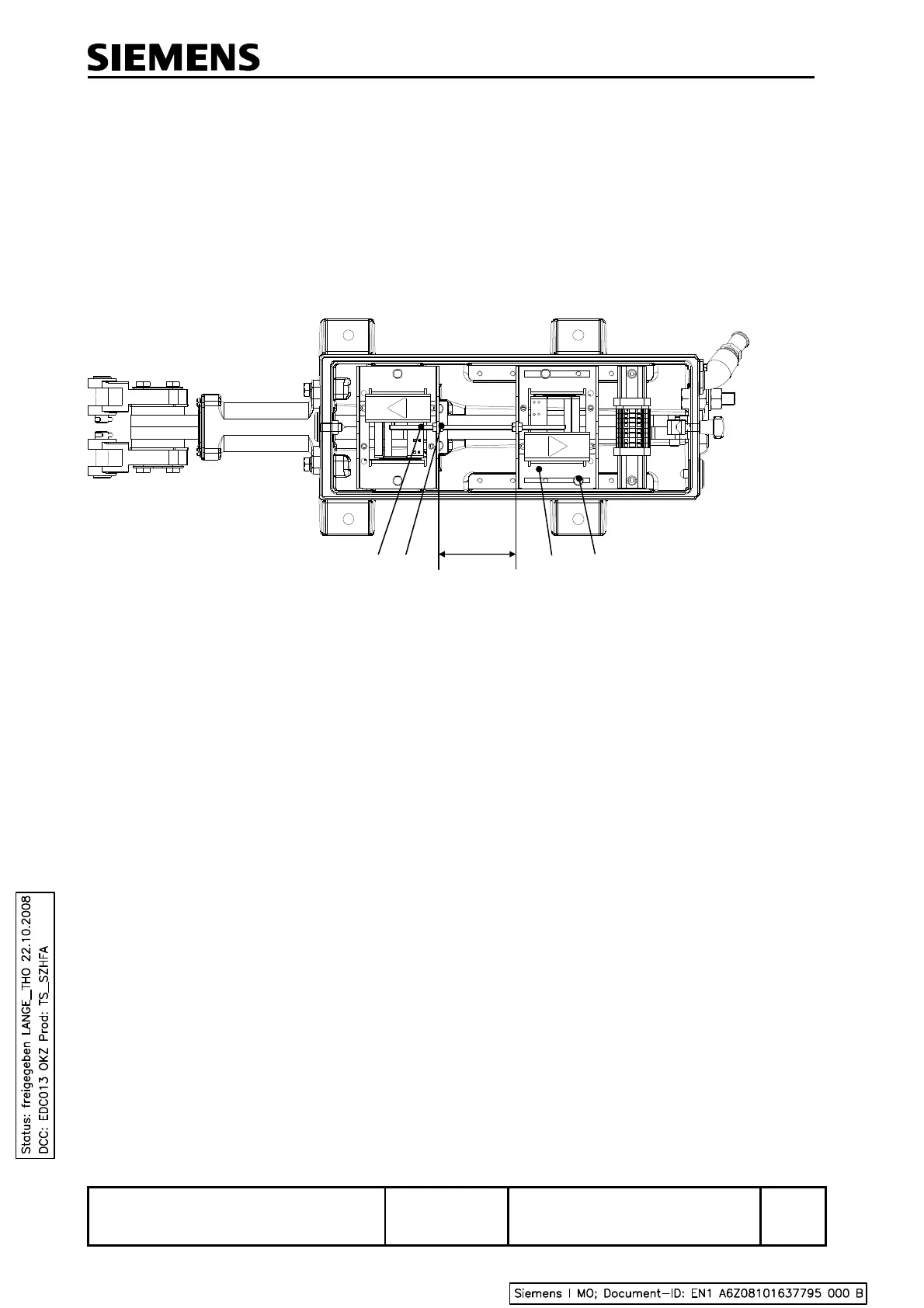
rods to the points. The movable contact arrangement must be shifted as shown in Figure 14.
The ELP 319 end position detector is supplied with a distance A = 94 mm, corresponding to a point
opening Z = 88 mm ± 8 mm.
A Distance
1 Threaded rod
2 Lock nut
3 Movable contact arrangement
4 Fastening bolt
Figure 14 Plan view of the open housing
Measure the point opening on site at the point of attachment of the detector rods to the point blades
and calculate the average.
Point opening Z
average
= 0.5 x ( Z
left
+ Z
right
)
Distance A for the adjustment of the movable contact arrangement is calculated using the following
formula:
Distance A [mm] = 182 – Z
average
1
2
3 4
A
 Loading...