Industry Mobility
Betriebsanleitung PZENTW A6Z08101637795/EN1/000/B 13
[7620] ELP 319 LANGE_THO A25000-X22-Q9-7-7620 of
DC013 20081022 Notice no.: 500000097465 33
Copyright (C) Siemens AG 1998 All Rights Reserved - 0000ZQ6U.doc
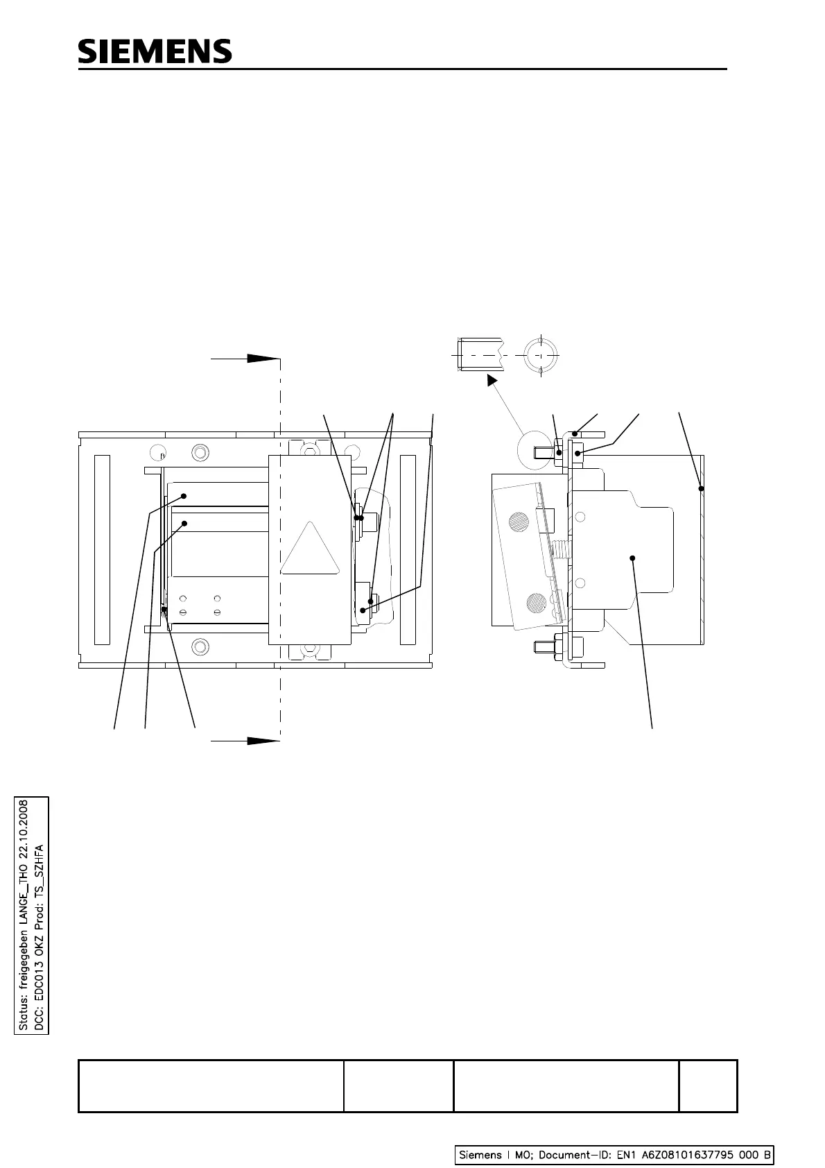
8.1.3 Contact Equipment
The contact equipment (see Figure 2) comprises contact arrangements 2 and 5, each consisting of a
base bearing the easily removable contact sets 3. Rockers with separate springs for each limit switch
are also mounted on the bases. Removable hoods protect the sets of contacts when the housing
cover is removed. Threaded rod 4 prevents the movable contact arrangement 2 from changing its set
position. The contacts of the limit switches 13 installed in contact arrangements 2 and 5 do not require
adjustment. The position of the switch axles within the slide notches is easily visible, thus facilitating
adjustment of the rodding and subsequent checking of the switch axles' position. The switch axles do
not touch the slide notches. Hence, vibrations from the slides are not transmitted to the switches (see
also Figure 4).
A
A
A-A
Figure 4 Contact arrangement
1)
1) Shank of screw upset to protect it against loss.
Upset the shank so that 14 mm of the thread remain usable.
 Loading...