Industry Mobility
Betriebsanleitung PZENTW A6Z08101637795/EN1/000/B 17
[7620] ELP 319 LANGE_THO A25000-X22-Q9-7-7620 of
DC013 20081022 Notice no.: 500000097465 33
Copyright (C) Siemens AG 1998 All Rights Reserved - 0000ZQ6U.doc
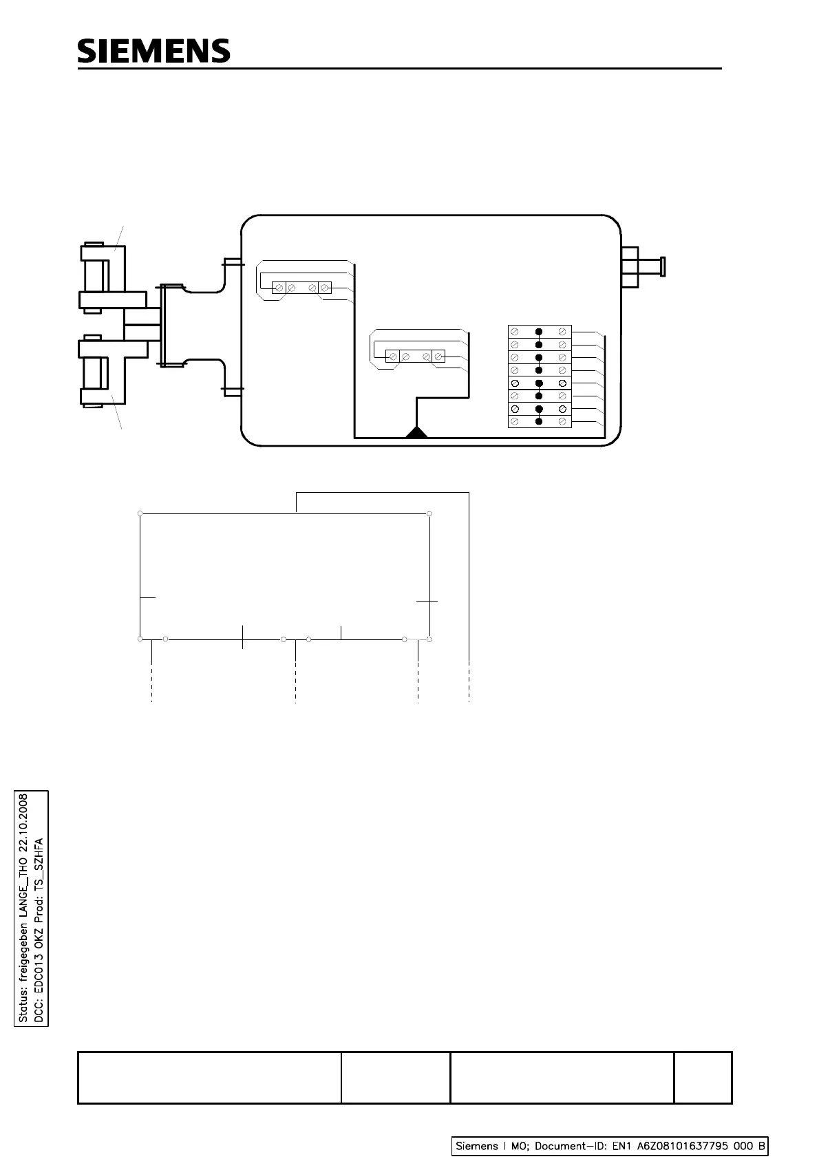
9.2 Circuit Diagrams
The circuit diagrams below show standard internal wirings of the ELP 319 end position detector.
Other wiring variants are available on request.
Contact position shown
corresponds to:
Rightmost position
of points for
left-hand mounting
Closed point blade
1
2
B
1B
1A
4A
4B
2B
2A
1
2
C
3
4
B
4
3
C
3B
3A
B
1
3
2 4
gy
bu
rd
bu
C
1
3
2 4
gy
bn
rd
bn
A
1
B
1
A
2
B
2
A
3
B
3
A
4
B
4
rd
rd
gy
gy
bn
bn
bu
bu
Open point blade
Leftmost position
of points for
right-hand mounting
Figure 7 Circuit diagram of the ELP 319 end position detector
(variant with eight series terminals)
 Loading...