LOGO! manual
EWA 4NEB 712 6006-02
20
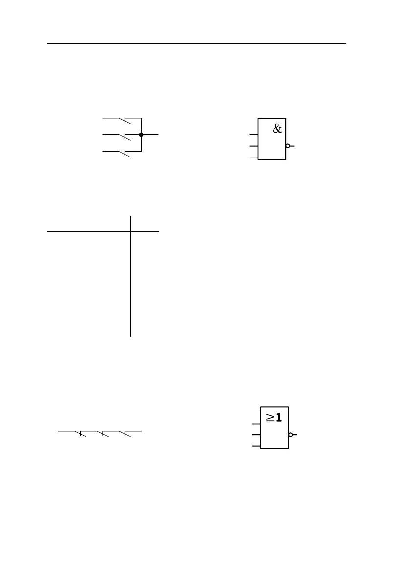
3.4.4 NAND
I1
I2
I3
Q
The parallel connection of a num-
ber of normally closed contacts is
represented in a circuit diagram as
follows:
In LOGO! this is a NAND block.
The symbol for it is as follows:
The block is called NAND because its output (Q) only has the state 0 if I1
and I2 and I3 have the state 1 (i.e. are closed).
Logic table for NAND
I1 I2 I3 Q
0 0 0 1
0011
0101
0111
1001
1011
1101
1110
3.4.5 NOR
I1
I2
I3
Q
The series connection of a number
of normally closed contacts is rep-
resented in a circuit diagram as
follows:
In LOGO! this is a NOR block. The
symbol for NOR is as follows:
The output of the NOR block is only switched on (state 1) when all the
inputs are switched off (state 0). As soon as any of the inputs is switched
on (state 1), the output is switched off.
Programming LOGO!
The following applies to NAND: x = 1
(x means the input is not used)
 Loading...

