LOGO! manual
EWA 4NEB 712 6006-02
88
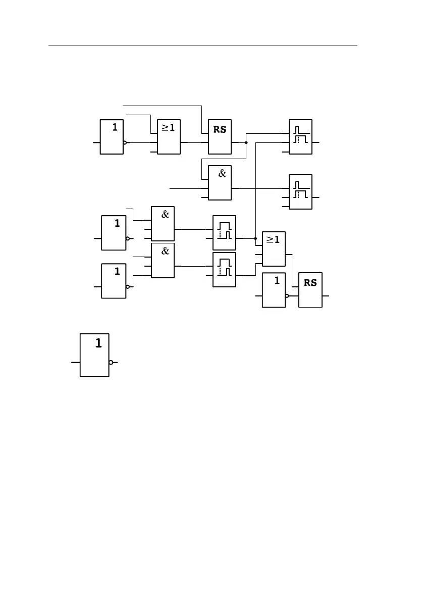
Functional diagram of the enhanced LOGO! solution
The ventilators at Q1 and Q2 are switched off as shown in the following
circuit:
x
T=
10 s
T=
30 s
Q1
Exhaust
air
ventilator
Q2
Fresh air
ventilator
On I1
I2
Off
Fault Q3
x
x
I3Exhaust air flow
monitor
I2Off
Fault
T=
10 s
T=
10 s
x
x
x
I3
Exhaust air flow
monitor
I4
Fresh air flow
monitor
Exhaust air ventilator Q1
Exhaust air ventilatorQ2
Q3
You can also generate a message via output Q4:
Q3
Fault
Q4
Message
The contacts of output Q4 are always closed when the system is running.
Relay Q4 does not release unless there is a power failure or a fault in the
system. This contact can be used for teleindication, for example.
Applications
 Loading...

