91
LOGO! manual
EWA 4NEB 712 6006-02
Components used
S K1 Master contactor
S K2 Master contactor
S S0 Stop switch
S S1 Open switch
S S2 Close switch
S S3 Open position switch
S S4 Closed position switch
S S5 Safety pressure bar
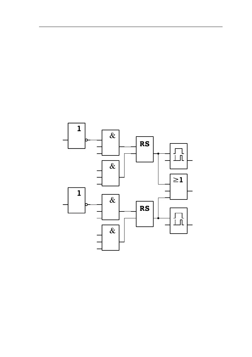
Functional diagram of the LOGO! solution
T=
5 s
T=
5 s
x
x
x
x
Q1
Open
Q3
Flashing
light
Q1
Close
I3
I4
I3
I6
I5
I1
I2
Q2
Q1
Safety bar
Gate is closed
Gate is open
Stop switch
Open start
switch
Stop switch
Close start
switch
The open and close start switches start the movement of the gate, provided
the gate is not currently moving in the opposite direction. The gate stops
moving when the stop switch is pressed or when it reaches a limit switch.
The gate is also prevented from closing by the safety bar.
Applications
 Loading...

