LOGO! installation and wiring
2.2 Installing/removing LOGO!
LOGO!
Manual, 04/2011, A5E03556174-01
39
2.2 Installing/removing LOGO!
Dimensions
The LOGO! installation dimensions are compliant with DIN 43880.
LOGO! can be snap-mounted to 35 mm DIN rails to EN 50022 or on the wall.
LOGO! width:
● LOGO! TD has a width of 128.2 mm, which corresponds to 8 subunits
● LOGO! 0BA6 Base Modules have a width of 72 mm, which corresponds to 4 subunits.
LOGO! 0BA7 Base Modules have a width of 107 mm, which corresponds to 6 subunits.
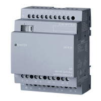
● LOGO! expansion modules have a width of 36 mm or 72 mm (DM16...), which
corresponds to 2 or 4 subunits
Note
The figures below show you an example of the installation and removal of a LOGO!
230RCE/LOGO!230RC and a digital module. The measures shown apply to all other
LOGO! Base Module versions and expansion modules.
WARNING
Always switch off power before you remove or insert an expansion module.

 Loading...


