Components
Components represent built-in functionality in Industrial IoT. Components are:
Asset Manager
Insights Hub Monitor
Settings
UTC Reporting
For the complete list and description of Components, refer to the documentation.
Data point
Data points refer to elements (variables), which allow values to be obtained from data sources
(OPC UA or S7 etc.). They are combined into a relevant aspect. For example, “temperature” and
“torque” are data points of an aspect “Energy_consumption”.
Data points are configured in "Asset Manager”. In “Insights Hub Monitor”, their values are
visualized as time series.
Data source
A data source is a physical element of a device, which can be monitored by Insights Hub.
For example: OPC UA Server, S7.
Event
In "Insights Hub Monitor", an event is a change of a datapoint state. Events are used for the
requests. With a rule it is possible to define the request, which will be created in Insights Hub
when the event is triggered.
Besides the monitoring rule, a description of event (e.g. “The limit is exceeded, this may indicate
damage in the pump”), the resulting action (e.g. “Please contact your hotline”) and priority
(urgent, important or info) can be lodged.
See also “request”, “rule".
Last Connection
"Last Connection" status in “Asset Manager” gives the information, when a MindConnect
Element was online for the last time.
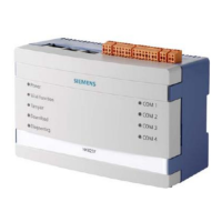
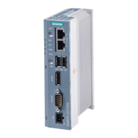
MindConnect Element
 Loading...