UM353-1 Controller and System Test
March 2003
10-1
10.0 CONTROLLER AND SYSTEM TEST
This section presents a series of steps to verify controller operation and to help a user become familiar with the
functionality of the controller. A new controller is shipped factory configured with either Factory Configured
Option FCO101 Single Loop Controller or a user-specified custom configuration. The following procedure is for
FCO101 with factory set parameter values. If a custom configuration was installed, or if you have configured the
controller, it may be necessary to modify the procedure to test all function blocks in that configuration.
To determine the current configuration of a controller, either:
• refer to your configuration documentation for that controller
• upload the configuration to a PC running the Graphical Configuration Software where the configuration can be
viewed
• enter the configuration mode and step through the configuration recording the configured function blocks and
entered parameter values
In the following steps, ‘press’ indicates a faceplate button (key).
10.1 CONTROLLER CONFIGURATION AND TEST
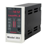
The purpose of this section is to configure and test the controller and to familiarize the user with the controller’s
faceplate pushbuttons, pulser, and displays. This section also introduces several configuration topics.
10.1.1 Connections and Power
1. Connect power to the controller. Refer to Controller nameplate for model number and then to Section 14 of
this manual for power requirements. Refer to Section 8 Installation for connections.
WARNING
Electrical shock hazard
Explosion hazard
Can cause death or injury
• Remove power from all wires and terminals before working on equipment.
• In potentially hazardous atmosphere, remove power from equipment before
connecting or disconnecting power, signal, or other circuit.
• Observe all pertinent regulations regarding installation in hazardous area.
2. Depending upon the configuration, connect test equipment to the I/O terminals.
FCO101 - This FCO has one 1-5 Volt analog input (AIN1), and one 4-20 mA analog output (AOUT1)
configured. To verify both of these outputs, and to simulate an analog input for subsequent steps, jumper the
terminals shown below. Connect a 250 ohm range resistor across the terminals shown below to convert the 4-
20 mA output to a 1-5 volt input. This will tie the valve output (horizontal bargraph) back in the loop as the
process input (P bargraph). Refer to Section 8 as necessary.
CONTROLLER JUMPER TERMINAL
INSTALL 250Ω AT TERMINALS
Model 352 Plus A4 to A7 From A4 to A5
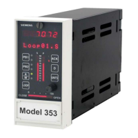
Models 353 and 354 17 to 20 From 20 to 21
Custom Configuration - Refer to Section 8 as necessary for any additional connections.
 Loading...
