Function Blocks UM353-1
March 2003
3-48
3.2.42 DOS__ - Digital Output State
DOS_ function blocks, in firmware 1.30 and higher, transmit up
to 16 on/off signals received from a controller block
interconnection to a remote node on the LonWorks network as a
single 16-bit word value. A maximum of 6 DOS blocks can be
used, up to the limit of nodes allowed on the Lon network or the
memory limit of the controller. Each use of the block will be
assigned a unique station wide ID (e.g. DOS01). The transmitted
value is of type SNVT_state and can be bound to a network
variable in a remote node that can receive a network variable of
this type. These blocks will be available when the LonWorks
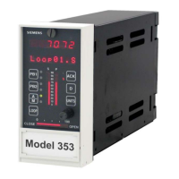
option board is installed in a 352P, 353, or 354N controller.
Each function block input has a mode associated with it. The
mode can be either NORMAL or FORCED. When using a PC
capable of sending LIL or Modbus commands, the mode can be
changed and the forced state can be assigned a high (1) or low (0)
value. The values accessible over the network are the two switch
inputs (N and F) and the position of the SPDT switch illustrated in
the block diagram. A mode of ‘0’ is Normal and ‘1’ is Forced.
The function block also has a quality status associated with it.
This status will go high (1) when the block determines it has lost
output communication with the Lon node bound to that input.
Input
0
0
Input 1
1
Input 2
2
Input 3
3
Input 4
4
Input 5
5
Input 6
6
Input 7
7
Input 8
8
Input 9
9
Input A
A
Input B
B
Input C
C
Input D
D
Input E
E
Input F
F
QS
Q
uality Status
DIGITAL OUTPUT _ STATE
DIGITAL OUTPUT
DOSnn
STATE
LONWorks
Network
U
N
V
NM
IN
PUT 0
INPUT 0
...............
loop tag.block tag.output (null)
I
N
P
U
TF
INPUT F
...............
loop tag.block tag.output (null)
nv*0
SNVT _lev_disc
nvoDODnn0
view
N
etwork
V
ariable
NUM
ber (nv*)
.. 1 to 2000
(*)
...........
BLOCK DIAGRAM
LON node r1
LON
LON network
option board
node u
SNVT_nv _
Station
0
nv z1
SNVT_
node r1, nv z1
nv_ binding
F
0
F
N
1
F
N
F
1
E
F
N
F
E
F
F
N
F
F
QS
 Loading...
